


20.1.1概述
简介
Stacking即堆叠是指将多台交换机设备组合在一起,虚拟化成一台交换设备,从而实现网络高可靠性和网络大数据量转发,同时简化网络管理。在堆叠中,有以下一些基本概念。
角色
堆叠中的单台交换机称为成员交换机,按照功能不同可以分为以下角色:
• 主交换机:负责管理整个堆叠,堆叠中只有一台主交换机。
• 备交换机:是主交换机的备份交换机。当主交换机故障时,备交换机会接替原主交换机的所有业务。堆叠中只有一台备交换机。
堆叠成员
用来标识和管理成员交换机。堆叠中所有交换机的堆叠成员ID都是唯一的。
堆叠优先级
堆叠优先级是成员交换机的一个属性,主要用于角色选举过程中确定成员交换机的角色,优先级越大表示优先级越高,当选为主交换机的可能性越大。
堆叠物理成员端口
堆叠物理成员端口,即被配置为堆叠模式的物理端口,用于堆叠成员交换机之间的连接。
堆叠端口
堆叠端口是一种专用于堆叠的逻辑端口,需要和堆叠物理成员端口绑定。一个堆叠端口可以与一个或多个堆叠物理成员端口绑定,以提高链路的宽带和可靠性。每台设备支持两个堆叠端口。
20.1.2配置举例
1.组网拓扑
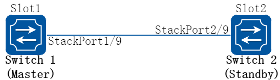
图20-1Stacking map
2.配置步骤
下面的例子描述了堆叠启动配置的过程,以两个交换机Switch1 和Switch2组成堆叠系统为例。
以下配置如未说明在哪个Switch配置,则表示所有Switch配置相同:
步骤 1进入配置模式
Switch# configure terminal
步骤 2配置stacking成员的slotid,重启生效
在Switch1配置
Switch(config)# stack slot 1
% Configuration will not take effect until save configuration and system reload
在Switch2配置
Switch(config)# stack slot 2
% Configuration will not take effect until save configuration and system reload
步骤 3使能stacking,重启生效
Switch(config)# stack enable
% Configuration will not take effect until save configuration and system reload.
![]() 使能stack或者去使能stack后并重启,端口相关的配置将被清空。
使能stack或者去使能stack后并重启,端口相关的配置将被清空。
步骤 4配置本板的stacking口
在Switch1配置
Switch(config)# interface stack-0-1
Switch(config-if)# member-port eth-0-9
在Switch2配置
Switch(config)# interface stack-0-1
Switch(config-if)# member-port eth-0-9
步骤 5退出配置模式
Switch(config)# end
步骤 6保存配置
Switch# write
步骤 7重启
Switch# reload
![]() 配置好后如果此时需要指定Switch1成为主交换机,在Switch1和Switch2间的堆叠线缆已经连接好的情况下,用户可以先启动Switch1 ,待Switch1启动完成后,再完成Switch2的重启。此时,Switch2以成员加入的流程加入堆叠系统,成为备交换机,而Switch1则成为主交换机。
配置好后如果此时需要指定Switch1成为主交换机,在Switch1和Switch2间的堆叠线缆已经连接好的情况下,用户可以先启动Switch1 ,待Switch1启动完成后,再完成Switch2的重启。此时,Switch2以成员加入的流程加入堆叠系统,成为备交换机,而Switch1则成为主交换机。
步骤 8命令验证
Switch# show stack
SlotID Role Board SwVersion MAC State Description
=========================================================================================
*+1 MASTER VPX6896M16_V2 7.0.3.55 001E.0822.FC83 RUNNING --
2 STANDBY VPX6896M16_V2 7.0.3.55 001E.0800.4574 RUNNING --
-----------------------------------------------------------------------------------------
* indicates the device is the master.
+ indicates the device through which the user logs in.
The System MAC of the Stacking is: 001E.0822.FC83
Mac persistent : yes
Domain ID : --
![]() 主设备和备设备均处于RUNNING状态,说明stacking已经建立成功。
主设备和备设备均处于RUNNING状态,说明stacking已经建立成功。
20.2.1概述
简介
Stacking支持删除线卡功能。
删除指定slotid线卡需要注意以下几点:
• 如果stacking已经使能,则只能在master上配置,如果stacking未使能则不允许配置。
• Slotid必须存在且不能是自己的slotid否则会返回错误。
• 删除线卡的同时会删除线卡对应已经创建的所有端口,如果线卡在线则会向该线卡发送消息使其重启。
20.2.2配置举例
步骤 1进入配置模式
Switch# configure terminal
步骤 2删除线卡配置
Switch(config)# stack release slot 3
![]() 使用stack release slot 3 命令删除线卡后,如果堆叠口连线没有断开,slot 3重启后仍会加入堆叠。如果堆叠系统需要恢复为单机环境,可以进行拆分堆叠操作。拆分堆叠首先需要去使能设备的堆叠功能,然后配置好每台设备的管理IP并保存配置。拆除线缆后,手动重启即可拆分堆叠。启动之后的设备将保存stacking系统下的非端口业务配置,端口相关的配置将被清空。
使用stack release slot 3 命令删除线卡后,如果堆叠口连线没有断开,slot 3重启后仍会加入堆叠。如果堆叠系统需要恢复为单机环境,可以进行拆分堆叠操作。拆分堆叠首先需要去使能设备的堆叠功能,然后配置好每台设备的管理IP并保存配置。拆除线缆后,手动重启即可拆分堆叠。启动之后的设备将保存stacking系统下的非端口业务配置,端口相关的配置将被清空。
步骤 3退出配置模式
Switch(config)# end
20.3.1概述
简介
双主检测DAD(Dual-Active Detect)是一种检测和处理堆叠分裂的协议,可以实现堆叠分裂的检测、冲突处理和故障恢复,降低堆叠分裂对业务的影响。 当堆叠线缆或者设备发生故障时,可能导致交换机之间失去通信,堆叠系统分裂成多个堆叠系统。但堆叠分裂后,其全局配置完全相同,会以相同的IP地址和MAC地址(堆叠系统MAC)与网络中的其他设备交互,这样就导致IP地址和MAC地址冲突,引起整个网络故障,此时可以依靠堆叠的双主检测来避免堆叠分裂后出现双主。
20.3.2配置举例
配置直连方式双主检测
1.组网拓扑
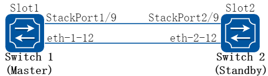
图20-2Stacking map
2.配置步骤
下面的例子描述了直连方式双主检测配置的过程,以两个交换机Switch1 和Switch2组成堆叠系统为例。
步骤 1进入配置模式
Switch# configure terminal
步骤 2配置堆叠域ID
Switch(config)# stack slot 1 domain 4
Switch(config)# stack slot 2 domain 4
步骤 3配置端口为直连方式的双主检测
Switch(config)# interface eth-1-12
Switch(config-if)# no shutdown
Switch(config-if)# stack dual-active detect mode direct
Warning: The interface will block common data packets, except BPDU packets. Continue? [no]y
Switch(config)# interface eth-2-12
Switch(config-if)# no shutdown
Switch(config-if)# stack dual-active detect mode direct
Warning: The interface will block common data packets, except BPDU packets. Continue? [no]y
步骤 4配置备板管理IP地址
Switch(config)# stack dual-active backup ip address 12.1.1.2/24 slot 1
Switch(config)# stack dual-active backup ip address 12.1.1.2/24 slot 2
步骤 5退出配置模式
Switch(config)# end
步骤 6命令验证
Switch# show stack dual-active
Stack domainID: 4
Dual-active conflict state: No
Excluded Ports(configurable):
- $$
Excluded Ports(can not be configured):
eth-1-9
eth-2-9
Dual-active direct detect mode: Enable
Dual-active direct detect interfaces configured:
eth-1-12 up (Physical) up (Protocol) 4 (PeerDoamain)
eth-2-12 up (Physical) up (Protocol) 4 (PeerDoamain)
Dual-active lacp detect mode: Disable
配置lacp方式双主检测
1.组网拓扑
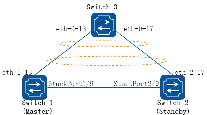
图20-3Stacking map
2.配置步骤
下面的例子描述了lacp方式双主检测配置的过程,以两个交换机Switch1 和Switch2组成堆叠系统为例。
步骤 1进入配置模式
Switch# configure terminal
步骤 2配置堆叠域ID
Switch(config)# stack slot 1 domain 4
Switch(config)# stack slot 2 domain 4
步骤 3配置端口为lacp方式的双主检测
Switch3(config)# interface eth-0-13
Switch3(config-if)# no shutdown
Switch3(config-if)# channel-group 1 mode active
Switch3(config-if)# interface eth-0-17
Switch3(config-if)# no shutdown
Switch3(config-if)# channel-group 1 mode active
Switch(config)# interface eth-1-13
Switch(config-if)# no shutdown
Switch(config-if)# channel-group 1 mode active
Switch(config-if)# interface eth-2-17
Switch(config-if)# no shutdown
Switch(config-if)# channel-group 1 mode active
Switch(config-if)# interface agg1
Switch(config-if)# stack dual-active detect mode lacp
步骤 4配置备板管理IP地址
Switch(config)# stack dual-active backup ip address 12.1.1.2/24 slot 1
Switch(config)# stack dual-active backup ip address 12.1.1.2/24 slot 2
步骤 5退出配置模式
Switch(config)# end
步骤 6命令验证
Switch# show stack dual-active
Stack domainID: 4
Dual-active conflict state: No
Excluded Ports(configurable):
- $$
Excluded Ports(can not be configured):
eth-1-9
eth-2-9
Dual-active direct detect mode: Disable
Dual-active lacp detect mode: Enable
Dual-active lacp detect interfaces configured:
agg1 Dual-active protocol status: up
eth-1-13 up (Physical) up (Protocol) 4 (PeerDoamain)
eth-2-17 up (Physical) up (Protocol) 4 (PeerDoamain)
![]() 如果当前堆叠系统上还没有配置业务,可以通过人为制造堆叠分裂来验证双主检测功能是否配置成功。在堆叠系统已有其他业务运行的情况下请勿进行此验证操作,否则会影响正在运行的业务。如果switch 3也是一台堆叠设备的话,switch 3的domain id必须与switch 1和switch 2组成的堆叠的domain id不一样,否则lacp mad无法正常工作。
如果当前堆叠系统上还没有配置业务,可以通过人为制造堆叠分裂来验证双主检测功能是否配置成功。在堆叠系统已有其他业务运行的情况下请勿进行此验证操作,否则会影响正在运行的业务。如果switch 3也是一台堆叠设备的话,switch 3的domain id必须与switch 1和switch 2组成的堆叠的domain id不一样,否则lacp mad无法正常工作。