


19.1.1概述
简介
本章节介绍如何配置LDP。
LDP的功能是为两个支持标签交换的路由器分发标签,目前软件系统支持的特性如下:
• 支持下游主动分发方式和自由保留模式。
• 支持配置标签控制方式。
• 支持lsr-id和传输地址的配置。
• 支持Target LDP。
• 支持分发标签过滤。
• 支持PHP模式和非PHP模式。
本篇手册将描述最基本的LDP配置,如果想更加深入的了解技术细节,建议阅读RFC3031,RFC3036。
19.1.2配置举例
配置LDP
1.组网拓扑
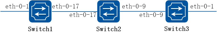
图19-1LSP map
2.配置步骤
下面的例子描述了如何使用LDP在Switch1到Switch3之间建立起一条LSP。
以下配置如未说明在哪个Switch配置,则表示所有Switch配置相同:
步骤 1进入配置模式
Switch# configure terminal
步骤 2进入接口配置模式,配置接口属性
Switch1的接口配置,接口需要使能ldp并且开启标签交换功能:
Switch1(config)# interface eth-0-17
Switch1(config-if)# no switchport
Switch1(config-if)# ip address 11.11.17.1/24
Switch1(config-if)# enable-ldp
Switch1(config-if)# label-switching
Switch1(config-if)# exit
Switch1(config)# interface loopback0
Switch1(config-if)# ip address 1.1.1.1/32
Switch1(config-if)# exit
Switch2的接口配置,接口需要使能ldp并且开启标签交换功能:
Switch2(config)# interface eth-0-17
Switch2(config-if)# no switchport
Switch2(config-if)# ip address 11.11.17.2/24
Switch2(config-if)# enable-ldp
Switch2(config-if)# label-switching
Switch2(config-if)# exit
Switch2(config)# interface eth-0-9
Switch2(config-if)# no switchport
Switch2(config-if)# ip address 11.11.9.1/24
Switch2(config-if)# enable-ldp
Switch2(config-if)# label-switching
Switch2(config-if)# exit
Switch2(config)# interface loopback0
Switch2(config-if)# ip address 2.2.2.2/32
Switch2(config-if)# exit
Switch3的接口配置,接口需要使能ldp并且开启标签交换功能:
Switch3(config)# interface eth-0-9
Switch3(config-if)# no switchport
Switch3(config-if)# ip address 11.11.9.2/24
Switch3(config-if)# enable-ldp
Switch3(config-if)# label-switching
Switch3(config-if)# exit
Switch3(config)# interface loopback0
Switch3(config-if)# ip address 3.3.3.3/32
Switch3(config-if)# exit
步骤 3使能ldp路由
Switch1的配置:
Switch1(config)# router ldp
Switch1(config-router)# router-id 1.1.1.1
Switch1(config-router)# exit
Switch2的配置:
Switch2(config)# router ldp
Switch2(config-router)# router-id 2.2.2.2
Switch2(config-router)# exit
Switch3的配置:
Switch3(config)# router ldp
Switch3(config-router)# router-id 3.3.3.3
Switch3(config-router)# exit
步骤 4使能rip路由
Switch(config)# router rip
Switch(config-router)# network 0.0.0.0/0
Switch(config-router)# exit
步骤 5退出配置模式
Switch(config)# end
步骤 6命令验证
查看Switch1中ldp session建立的状态:
Switch1# show ldp session
Peer IP Address IF Name My Role State KeepAlive
2.2.2.2 eth-0-17 Passive OPERATIONAL 30
查看Switch2中ldp session建立的状态:
Switch2# show ldp session
Peer IP Address IF Name My Role State KeepAlive
3.3.3.3 eth-0-9 Active OPERATIONAL 30
1.1.1.1 eth-0-17 Active OPERATIONAL 30
查看Switch3中ldp session建立的状态:
Switch3# show ldp session
Peer IP Address IF Name My Role State KeepAlive
2.2.2.2 eth-0-9 Passive OPERATIONAL 30
19.2.1概述
简介
MPLS即多协议标签交换,能够适用于任何网络层,但在这篇文档里,我们只关注MPLS在IP网络中的应用。
在通常的IP网络中,报文头部中包含了很多信息来决定如何选择下一跳,如何选择分为如下两个步骤:首先将条目分成不同的转发等价类,接着将指定的转发等价类映射到某条下一跳上。该过程是不可逆的,对于选定了下一跳的报文,我们不关心他为何被映射到这条转发等价类中。在某个特定的节点,所有同一转发等价类的报文都将通过同一条路径进行转发(如果存在ECMP的情况,他们会从该组路径中选择一条进行转发)。根据最长匹配的原则,路由器可能会将两个不同的报文映射到同一条转发等价类中。在一个报文遍历整个网络时,每一跳都会重新解析报文,并将报文映射到一个指定的转发等价类中。
在MPLS网络中,只需要进行一次报文到转发等价类的映射,因为当报文进入网络后,对于指定的FEC会映射到一个标签上,报文会携带该标签转发到下一跳,在接下来的转发过程中,就不需要重新解析报文头部来报文映射到转发等价类中,只需使用标签作为索引进行查找转发,使用新的标签替换旧的标签,将报文继续进行转发。
在下面的例子中可以发现,一旦报文指定了转发等价类,接下来的转发都是依靠标签的了。
19.2.2配置举例
配置MPLS LSP
1.组网拓扑
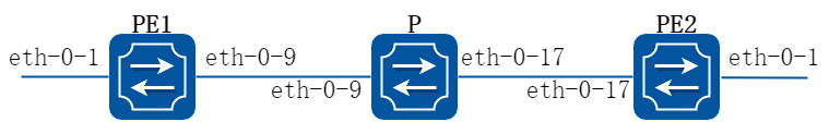
图19-2MPLS LSP 模型
2.配置步骤
下面的例子描述了如何配置MPLS LSP。
以下配置如未说明在哪个Switch配置,则表示所有Switch配置相同:
步骤 1进入配置模式
Switch# configure terminal
步骤 2进入接口配置模式,配置接口属性
PE1的接口配置,接口需要开启标签交换功能:
PE1(config)# interface eth-0-9
PE1(config-if)# no switchport
PE1(config-if)# ip address 11.11.9.1/24
PE1(config-if)# label-switching
PE1(config-if)# exit
PE1(config)# interface eth-0-1
PE1(config-if)# no switchport
PE1(config-if)# ip address 10.10.10.1/24
PE1(config-if)# label-switching
PE1(config-if)# exit
P的接口配置,接口需要开启标签交换功能:
P(config)# interface eth-0-9
P(config-if)# no switchport
P(config-if)# ip address 11.11.9.2/24
P(config-if)# label-switching
P(config-if)# exit
P(config)# interface eth-0-17
P(config-if)# no switchport
P(config-if)# ip address 11.11.17.2/24
P(config-if)# label-switching
P(config-if)# exit
PE2的接口配置,接口需要开启标签交换功能:
PE2(config)# interface eth-0-17
PE2(config-if)# no switchport
PE2(config-if)# ip address 11.11.17.3/24
PE2(config-if)# label-switching
PE2(config-if)# exit
PE2(config)# interface eth-0-1
PE2(config-if)# no switchport
PE2(config-if)# ip address 20.20.20.1/24
PE2(config-if)# label-switching
PE2(config-if)# exit
步骤 3配置静态ftn/ilm
PE1的静态ftn:
PE1(config)# mpls ftn-entry 172.22.4.1/24 100 11.11.9.2
P的静态ilm:
P(config)# mpls ilm-entry swap 100 11.11.17.3 200
PE2的静态ilm:
PE2(config)# mpls ilm-entry php 200 20.20.20.2
步骤 4退出配置模式
Switch(config)# end
步骤 5命令验证
显示PE1上的ftn表项:
PE1# show mpls ftn-database
Codes: > - selected FTN, p - stale FTN, B - BGP FTN, K - CLI FTN,
L - LDP FTN, R - RSVP-TE FTN, S - SNMP FTN, I - IGP-Shortcut,
U - unknown FTN
Code FEC Out-Label Nexthop Out-Intf
K> 172.22.4.0/24 100 11.11.9.2 eth-0-9
显示P上的ilm表项:
P# show mpls ilm-database
Codes: > - selected ILM, p - stale ILM, B - BGP ILM, K - CLI ILM,
L - LDP ILM, R - RSVP-TE ILM, S - SNMP ILM, I - IGP-Shortcut,
U - unknown ILM
Code FEC I/O Label Nexthop Out-Intf
K> 0.0.0.0/0 100/200 11.11.17.3 eth-0-17
显示PE2上的ilm表项:
PE2# show mpls ilm-database
Codes: > - selected ILM, p - stale ILM, B - BGP ILM, K - CLI ILM,
L - LDP ILM, R - RSVP-TE ILM, S - SNMP ILM, I - IGP-Shortcut,
U - unknown ILM
Code FEC I/O Label Nexthop Out-Intf
K> 0.0.0.0/0 200/3 20.20.20.2 eth-0-1
19.3.1概述
简介
本章节描述了如何配置VPLS。虚拟专用局域网(VPLS),其核心思想是利用信令协议在VPLS实例中的PE(运营商边缘路由器)节点之间建立及维护PW(伪线),将二层协议帧封装后在PW上传输、交换,使广域范围内多个局域网在数据链路层面被整合为一张网络,向用户提供虚拟的以太网服务。
19.3.2配置举例
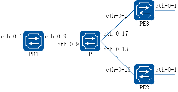
图19-3VPLS 模型
使用LDP配置VPLS
下面的例子描述了如何使用LDP配置VPLS。
以下配置如未说明在哪个Switch配置,则表示所有Switch配置相同:
步骤 1进入配置模式
Switch# configure terminal
步骤 2进入接口配置模式,配置接口属性
PE1的接口配置,eth-0-9需要使能ldp并且开启标签交换功能:
PE1(config)# interface eth-0-9
PE1(config-if)# no switchport
PE1(config-if)# ip address 11.11.9.1/24
PE1(config-if)# enable-ldp
PE1(config-if)# label-switching
PE1(config-if)# exit
PE1(config)# interface loopback 0
PE1(config-if)# ip address 11.11.1.1/32
PE1(config-if)# exit
PE2的接口配置,eth-0-13需要使能ldp并且开启标签交换功能:
PE2(config)# interface eth-0-13
PE2(config-if)# no switchport
PE2(config-if)# ip address 11.11.13.4/24
PE2(config-if)# enable-ldp
PE2(config-if)# label-switching
PE2(config-if)# exit
PE2(config)# interface loopback 0
PE2(config-if)# ip address 11.11.4.4/32
PE2(config-if)# exit
PE3的接口配置,eth-0-17需要使能ldp并且开启标签交换功能:
PE3(config)# interface eth-0-17
PE3(config-if)# no switchport
PE3(config-if)# ip address 11.11.17.3/24
PE3(config-if)# enable-ldp
PE3(config-if)# label-switching
PE3(config-if)# exit
PE3(config)# interface loopback 0
PE3(config-if)# ip address 11.11.3.3/32
PE3(config-if)# exit
P的接口配置,接口需要使能ldp并且开启标签交换功能:
P(config)# interface eth-0-9
P(config-if)# no switchport
P(config-if)# ip address 11.11.9.2/24
P(config-if)# enable-ldp
P(config-if)# label-switching
P(config-if)# exit
P(config)# interface eth-0-13
P(config-if)# no switchport
P(config-if)# ip address 11.11.13.2/24
P(config-if)# enable-ldp
P(config-if)# label-switching
P(config-if)# exit
P(config)# interface eth-0-17
P(config-if)# no switchport
P(config-if)# ip address 11.11.17.2/24
P(config-if)# enable-ldp
P(config-if)# label-switching
P(config-if)# exit
P(config)# interface loopback 0
P(config-if)# ip address 11.11.2.2/32
P(config-if)# exit
步骤 3使能ldp路由
PE1的LDP配置:
PE1(config)# router ldp
PE1(config-router)# router-id 11.11.1.1
PE1(config-router)# targeted-peer 11.11.3.3
PE1(config-router)# targeted-peer 11.11.4.4
PE1(config-router)# transport-address 11.11.1.1
PE1(config-router)# exit
PE2的LDP配置:
PE2(config)# router ldp
PE2(config-router)# router-id 11.11.4.4
PE2(config-router)# transport-address 11.11.4.4
PE2(config-router)# targeted-peer 11.11.1.1
PE2(config-router)# targeted-peer 11.11.3.3
PE2(config-router)# exit
PE3的LDP配置:
PE3(config)# router ldp
PE3(config-router)# router-id 11.11.3.3
PE3(config-router)# transport-address 11.11.3.3
PE3(config-router)# targeted-peer 11.11.1.1
PE3(config-router)# targeted-peer 11.11.4.4
PE3(config-router)# exit
P的LDP配置:
P(config)# router ldp
P(config-router)# router-id 11.11.2.2
P(config-router)# exit
步骤 4使能rip路由
Switch(config)# router rip
Switch(config-router)# network 11.11.1.1/16
Switch(config-router)# exit
步骤 5配置mpls vpls 实例
PE1, PE2, PE3均配置PW侧为raw模式,并指定vpls peer。
PE1的VPLS实例配置:
PE1(config)# mpls vpls v1 100
PE1(config-vpls)# vpls-peer 11.11.3.3 raw
PE1(config-vpls)# vpls-peer 11.11.4.4 raw
PE1(config-vpls)# exit
PE2的VPLS实例配置:
PE2(config)# mpls vpls v4 100
PE2(config-vpls)# vpls-peer 11.11.1.1 raw
PE2(config-vpls)# vpls-peer 11.11.3.3 raw
PE2(config-vpls)# exit
PE3的VPLS实例配置:
PE3(config)# mpls vpls v3 100
PE3(config-vpls)# vpls-peer 11.11.1.1 raw
PE3(config-vpls)# vpls-peer 11.11.4.4 raw
PE3(config-vpls)# exit
步骤 6在端口上绑定mpls vpls 实例
PE1, PE2, PE3的AC侧均配置为VLAN接入。
PE1的接口配置:
PE1(config)# interface eth-0-1
PE1(config-if)# switchport mode trunk
PE1(config-if)# mpls-vpls v1 vlan 2
PE1(config-if)# exit
PE2的接口配置:
PE2(config)# interface eth-0-1
PE2(config-if)# switchport mode trunk
PE2(config-if)# mpls-vpls v4 vlan 2
PE2(config-if)# exit
PE3的接口配置:
PE3(config)# interface eth-0-1
PE3(config-if)# switchport mode trunk
PE3(config-if)# mpls-vpls v3 vlan 2
PE3(config-if)# exit
步骤 7退出配置模式
Switch(config)# end
步骤 8命令验证
使用show ldp session和show mpls vpls mesh命令来查看VPLS的完整信息。show ldp session可以得到当前LDP session运行的状态,show mpls vpls mesh可以看到vpls peer的状态以及vpls所使用的内层label,pw的模式。
PE1显示结果:
PE1# show ldp session
Peer IP Address IF Name My Role State KeepAlive
11.11.3.3 eth-0-9 Passive OPERATIONAL 30
11.11.4.4 eth-0-9 Passive OPERATIONAL 30
11.11.2.2 eth-0-9 Passive OPERATIONAL 30
PE1# show mpls vpls mesh
VPLS-ID Peer Addr/name In-Label Out-Intf Out-Label Type St
100 11.11.3.3/- 32768 eth-0-9 32768 RAW Up
100 11.11.4.4/- 32773 eth-0-9 32768 RAW Up
PE2显示结果:
PE2# show ldp session
Peer IP Address IF Name My Role State KeepAlive
11.11.1.1 eth-0-13 Active OPERATIONAL 30
11.11.3.3 eth-0-13 Active OPERATIONAL 30
11.11.2.2 eth-0-13 Passive OPERATIONAL 30
PE2# show mpls vpls mesh
VPLS-ID Peer Addr/name In-Label Out-Intf Out-Label Type St
100 11.11.1.1/- 32768 eth-0-13 32773 RAW Up
100 11.11.3.3/- 32769 eth-0-13 32770 RAW Up
PE3显示结果:
PE3# show ldp session
Peer IP Address IF Name My Role State KeepAlive
11.11.1.1 eth-0-17 Active OPERATIONAL 30
11.11.4.4 eth-0-17 Passive OPERATIONAL 30
11.11.2.2 eth-0-17 Passive OPERATIONAL 30
PE3# show mpls vpls mesh
VPLS-ID Peer Addr/name In-Label Out-Intf Out-Label Type St
100 11.11.1.1/- 32768 eth-0-17 32768 RAW Up
100 11.11.4.4/- 32770 eth-0-17 32769 RAW Up
P显示结果:
P# show ldp session
Peer IP Address IF Name My Role State KeepAlive
11.11.1.1 eth-0-9 Active OPERATIONAL 30
11.11.3.3 eth-0-17 Active OPERATIONAL 30
11.11.4.4 eth-0-13 Active OPERATIONAL 30
配置静态VPLS
下面的例子描述了如何配置静态VPLS。
以下配置如未说明在哪个Switch配置,则表示所有Switch配置相同:
步骤 1进入配置模式
Switch# configure terminal
步骤 2进入接口配置模式,配置接口属性
PE1的接口配置,eth-0-9需要开启标签交换功能:
PE1(config)# interface eth-0-9
PE1(config-if)# no switchport
PE1(config-if)# ip address 11.11.9.1/24
PE1(config-if)# label-switching
PE1(config-if)# exit
PE2的接口配置,eth-0-13需要开启标签交换功能:
PE2(config)# interface eth-0-13
PE2(config-if)# no switchport
PE2(config-if)# ip address 11.11.13.1/24
PE2(config-if)# label-switching
PE2(config-if)# exit
PE3的接口配置,eth-0-17需要开启标签交换功能:
PE3(config)# interface eth-0-17
PE3(config-if)# no switchport
PE3(config-if)# ip address 11.11.17.1/24
PE3(config-if)# label-switching
PE3(config-if)# exit
P的接口配置,eth-0-9, eth-0-13和eth-0-17均需要开启标签交换功能:
P(config)# interface eth-0-9
P(config-if)# no switchport
P(config-if)# ip address 11.11.9.2/24
P(config-if)# label-switching
P(config-if)# exit
P(config)# interface eth-0-17
P(config-if)# no switchport
P(config-if)# ip address 11.11.17.2/24
P(config-if)# label-switching
P(config-if)# exit
P(config)# interface eth-0-13
P(config-if)# no switchport
P(config-if)# ip address 11.11.13.2/24
P(config-if)# label-switching
P(config-if)# exit
步骤 3配置ftn条目
PE1的接口配置:
PE1(config)# mpls ftn-entry 11.11.17.1/24 97 11.11.9.2
PE1(config)# mpls ftn-entry 11.11.13.1/24 93 11.11.9.2
PE2的接口配置:
PE2(config)# mpls ftn-entry 11.11.9.1/32 44 11.11.13.2
PE3的接口配置:
PE3(config)#mpls ftn-entry 11.11.9.1/32 33 11.11.17.2
步骤 4配置mpls vpls 实例
PE1, PE2, PE3均配置PW侧为raw模式,并指定vpls peer。
PE1的VPLS实例配置:
PE1(config)# mpls vpls vpls1 1
PE1(config-vpls)# vpls-peer 11.11.17.1 raw manual
PE1(config-vpls)# vpls-peer 11.11.13.1 raw manual
PE2的VPLS实例配置:
PE2(config)# mpls vpls vpls1 1
PE2(config-vpls)# vpls-peer 11.11.9.1 raw manual
PE3的VPLS实例配置:
PE3(config)# mpls vpls vpls1 1
PE3(config-vpls)# vpls-peer 11.11.9.1 raw manual
步骤 5在端口上绑定mpls vpls 实例
PE1, PE2, PE3的AC侧均配置为VLAN接入。
PE1的接口配置:
PE1(config)# interface eth-0-1
PE1(config-if)# switchport mode trunk
PE1(config-if)# mpls-vpls vpls1 vlan 100
PE1(config-if)# exit
PE2的接口配置:
PE2(config)# interface eth-0-1
PE2(config-if)# switchport mode trunk
PE2(config-if)# mpls-vpls vpls1 vlan 100
PE2(config-if)# exit
PE3的接口配置:
PE3(config)#interface eth-0-1
PE3(config-if)# switchport mode trunk
PE3(config-if)# mpls-vpls vpls1 vlan 100
PE3(config-if)# exit
步骤 6配置 VPLS FIB
PE1的VPLS FIB:
PE1(config)# vpls-fib-add vpls1 peer 11.11.17.1 103 31
PE1(config)# vpls-fib-add vpls1 peer 11.11.13.1 102 201
PE2的VPLS FIB:
PE2(config)# vpls-fib-add vpls1 peer 11.11.9.1 201 102
PE3的VPLS FIB:
PE3(config)# vpls-fib-add vpls1 peer 11.11.9.1 31 103
步骤 7配置静态ilm
P的静态ilm:
P(config)# mpls ilm-entry php 97 11.11.17.1
P(config)# mpls ilm-entry php 93 11.11.13.1
P(config)# mpls ilm-entry php 33 11.11.9.1
P(config)# mpls ilm-entry php 44 11.11.9.1
步骤 8退出配置模式
Switch(config)# end
步骤 9命令验证
使用show mpls vpls mesh可以看到vpls peer的状态以及vpls所使用的内层label,pw的模式。
PE1显示结果:
PE1# show mpls vpls mesh
VPLS-ID Peer Addr/name In-Label Out-Intf Out-Label Type St
1 11.11.13.1/- 102 eth-0-9 201 RAW Up
1 11.11.17.1/- 103 eth-0-9 31 RAW Up
PE2显示结果:
PE2# show mpls vpls mesh
VPLS-ID Peer Addr/name In-Label Out-Intf Out-Label Type St
1 11.11.9.1/- 201 eth-0-13 102 RAW Up
PE3显示结果:
PE3# show mpls vpls mesh
VPLS-ID Peer Addr/name In-Label Out-Intf Out-Label Type St
1 11.11.9.1/- 31 eth-0-17 103 RAW Up
P显示结果:
P# show mpls ilm-database
Codes: > - selected ILM, p - stale ILM, B - BGP ILM, K - CLI ILM,
L - LDP ILM, R - RSVP-TE ILM, S - SNMP ILM, I - IGP-Shortcut,
U - unknown ILM
Code FEC I/O Label Nexthop Out-Intf
K> 0.0.0.0/0 33/3 11.11.9.1 eth-0-9
K> 0.0.0.0/0 44/3 11.11.9.1 eth-0-9
K> 0.0.0.0/0 93/3 11.11.13.1 eth-0-13
K> 0.0.0.0/0 97/3 11.11.17.1 eth-0-17
使用VPLS透传二层协议报文
通过网络服务提供商连接的处于不同地域的用户,本地和远端之间需要运行STP等二层协议,就需要网络服务提供商能够透传STP等二层协议。 如下例子展示了如何使用VPLS来透传二层报文,以下配置基于VPLS模型拓扑图。
以下配置如未说明在哪个Switch配置,则表示所有Switch配置相同:
步骤 1进入配置模式
Switch# configure terminal
步骤 2全局使能L2 protocol
Switch(config)# l2protocol enable
步骤 3进入接口配置模式,配置接口属性
PE1的接口配置,eth-0-9需要使能ldp并且开启标签交换功能:
PE1(config)# interface eth-0-9
PE1(config-if)# no switchport
PE1(config-if)# ip address 11.11.9.1/24
PE1(config-if)# enable-ldp
PE1(config-if)# label-switching
PE1(config-if)# exit
PE1(config)# interface loopback 0
PE1(config-if)# ip address 11.11.1.1/32
PE1(config-if)# exit
PE2的接口配置,eth-0-13需要使能ldp并且开启标签交换功能:
PE2(config)# interface eth-0-13
PE2(config-if)# no switchport
PE2(config-if)# ip add 11.11.13.4/24
PE2(config-if)# enable-ldp
PE2(config-if)# label-switching
PE2(config-if)# exit
PE2(config)# interface loopback 0
PE2(config-if)# ip address 11.11.4.4/32
PE2(config-if)# exit
PE3的接口配置,eth-0-17需要使能ldp并且开启标签交换功能:
PE3(config)# interface eth-0-17
PE3(config-if)# no switchport
PE3(config-if)# ip address 11.11.17.3/24
PE3(config-if)# enable-ldp
PE3(config-if)# label-switching
PE3(config-if)# exit
PE3(config)# interface loopback 0
PE3(config-if)# ip address 11.11.3.3/32
PE3(config-if)# exit
P的接口配置,接口需要使能ldp并且开启标签交换功能:
P(config)# interface eth-0-9
P(config-if)# no switchport
P(config-if)# ip address 11.11.9.2/24
P(config-if)# enable-ldp
P(config-if)# label-switching
P(config-if)# exit
P(config)# interface eth-0-13
P(config-if)# no switchport
P(config-if)# ip address 11.11.13.2/24
P(config-if)# enable-ldp
P(config-if)# label-switching
P(config-if)# exit
P(config)# interface eth-0-17
P(config-if)# no switchport
P(config-if)# ip address 11.11.17.2/24
P(config-if)# enable-ldp
P(config-if)# label-switching
P(config-if)# exit
P(config)# interface loopback 0
P(config-if)# ip address 11.11.2.2/32
P(config-if)# exit
步骤 4使能ldp路由
PE1的LDP配置:
PE1(config)# router ldp
PE1(config-router)# router-id 11.11.1.1
PE1(config-router)# targeted-peer 11.11.3.3
PE1(config-router)# targeted-peer 11.11.4.4
PE1(config-router)# transport-address 11.11.1.1
PE1(config-router)# exit
PE2的LDP配置:
PE2(config)# router ldp
PE2(config-router)# router-id 11.11.4.4
PE2(config-router)# transport-address 11.11.4.4
PE2(config-router)# targeted-peer 11.11.1.1
PE2(config-router)# targeted-peer 11.11.3.3
PE2(config-router)# exit
PE3的LDP配置:
PE3(config)# router ldp
PE3(config-router)# router-id 11.11.3.3
PE3(config-router)# transport-address 11.11.3.3
PE3(config-router)# targeted-peer 11.11.1.1
PE3(config-router)# targeted-peer 11.11.4.4
PE3(config-router)# exit
P的LDP配置:
P(config)# router ldp
P(config-router)# router-id 11.11.2.2
P(config-router)# exit
步骤 5使能rip路由
PE1、PE2、PE3的RIP配置:
Switch(config)# router rip
Switch(config-router)# network 11.11.1.1/16
Switch(config-router)# exit
步骤 6配置mpls vpls 实例
PE1, PE2, PE3均配置PW侧为raw模式,并指定vpls peer。
PE1的VPLS实例配置:
PE1(config)# mpls vpls v1 100
PE1(config-vpls)# vpls-peer 11.11.3.3 raw
PE1(config-vpls)# vpls-peer 11.11.4.4 raw
PE1(config-vpls)# exit
PE2的VPLS实例配置:
PE2(config)# mpls vpls v4 100
PE2(config-vpls)# vpls-peer 11.11.1.1 raw
PE2(config-vpls)# vpls-peer 11.11.3.3 raw
PE2(config-vpls)# exit
PE3的VPLS实例配置:
PE3(config)# mpls vpls v3 100
PE3(config-vpls)# vpls-peer 11.11.1.1 raw
PE3(config-vpls)# vpls-peer 11.11.4.4 raw
PE3(config-vpls)# exit
步骤 7在端口上绑定mpls vpls 实例
PE1, PE2, PE3的AC侧均配置为ethernet接入。
PE1的接口配置:
PE1(config)# interface eth-0-1
PE1(config-if)# mpls-vpls v1 ethernet
PE1(config-if)# l2protocol stp tunnel
PE1(config-if)# exit
PE2的接口配置:
PE2(config)# interface eth-0-1
PE2(config-if)# mpls-vpls v4 ethernet
PE2(config-if)# l2protocol stp tunnel
PE2(config-if)# exit
PE3的接口配置:
PE3(config)# interface eth-0-1
PE3(config-if)# mpls-vpls v3 ethernet
PE3(config-if)# l2protocol stp tunnel
PE3(config-if)# exit
步骤 8退出配置模式
Switch(config)# end
配置VPLS静态MAC地址
在一个VSI内,如果PE节点收到了一个未知目的MAC的报文,则PE将会flood该报文。用户可以配置静态MAC表项来将带有指定目的MAC的报文发往指定的目的端口,指定PW或者丢弃。 以下举例了如何配置静态MAC,配置拓扑配置基于VPLS模型拓扑。
以下配置如未说明在哪个Switch配置,则表示所有Switch配置相同:
步骤 1进入配置模式
Switch# configure terminal
步骤 2进入接口配置模式,配置接口属性
PE1的接口配置,eth-0-9需要使能ldp并且开启标签交换功能:
PE1(config)# interface eth-0-9
PE1(config-if)# no switchport
PE1(config-if)# ip address 11.11.9.1/24
PE1(config-if)# enable-ldp
PE1(config-if)# label-switching
PE1(config-if)# exit
PE1(config)# interface loopback 0
PE1(config-if)# ip address 11.11.1.1/32
PE1(config-if)# exit
PE2的接口配置,eth-0-13需要使能ldp并且开启标签交换功能:
PE2(config)# interface eth-0-13
PE2(config-if)# no switchport
PE2(config-if)# ip add 11.11.13.4/24
PE2(config-if)# enable-ldp
PE2(config-if)# label-switching
PE2(config-if)# exit
PE2(config)# interface loopback 0
PE2(config-if)# ip address 11.11.4.4/32
PE2(config-if)# exit
PE3的接口配置,eth-0-17需要使能ldp并且开启标签交换功能:
PE3(config)# interface eth-0-17
PE3(config-if)# no switchport
PE3(config-if)# ip address 11.11.17.3/24
PE3(config-if)# enable-ldp
PE3(config-if)# label-switching
PE3(config-if)# exit
PE3(config)# interface loopback 0
PE3(config-if)# ip address 11.11.3.3/32
PE3(config-if)# exit
P的接口配置,接口需要使能ldp并且开启标签交换功能:
P(config)# interface eth-0-9
P(config-if)# no switchport
P(config-if)# ip address 11.11.9.2/24
P(config-if)# enable-ldp
P(config-if)# label-switching
P(config-if)# exit
P(config)# interface eth-0-13
P(config-if)# no switchport
P(config-if)# ip address 11.11.13.2/24
P(config-if)# enable-ldp
P(config-if)# label-switching
P(config-if)# exit
P(config)# interface eth-0-17
P(config-if)# no switchport
P(config-if)# ip address 11.11.17.2/24
P(config-if)# enable-ldp
P(config-if)# label-switching
P(config-if)# exit
P(config)# interface loopback 0
P(config-if)# ip address 11.11.2.2/32
P(config-if)# exit
步骤 3使能ldp路由
PE1的LDP配置:
PE1(config)# router ldp
PE1(config-router)# router-id 11.11.1.1
PE1(config-router)# targeted-peer 11.11.3.3
PE1(config-router)# targeted-peer 11.11.4.4
PE1(config-router)# transport-address 11.11.1.1
PE1(config-router)# exit
PE2的LDP配置:
PE2(config)# router ldp
PE2(config-router)# router-id 11.11.4.4
PE2(config-router)# transport-address 11.11.4.4
PE2(config-router)# targeted-peer 11.11.1.1
PE2(config-router)# targeted-peer 11.11.3.3
PE2(config-router)# exit
PE3的LDP配置:
PE3(config)# router ldp
PE3(config-router)# router-id 11.11.3.3
PE3(config-router)# transport-address 11.11.3.3
PE3(config-router)# targeted-peer 11.11.1.1
PE3(config-router)# targeted-peer 11.11.4.4
PE3(config-router)# exit
P的LDP配置:
P(config)# router ldp
P(config-router)# router-id 11.11.2.2
P(config-router)# exit
步骤 4使能rip路由
Switch(config)# router rip
Switch(config-router)# network 11.11.1.1/16
Switch(config-router)# exit
步骤 5配置mpls vpls 实例
PE1, PE2, PE3均配置PW侧为raw模式,并指定vpls peer。
PE1的VPLS实例配置:
PE1(config)# mpls vpls v1 100
PE1(config-vpls)# vpls-peer 11.11.3.3 raw
PE1(config-vpls)# vpls-peer 11.11.4.4 raw
PE1(config-vpls)# mac-address-table 0000.0000.0001 forward eth-0-1
PE1(config-vpls)# mac-address-table 0000.0000.0003 forward peer 11.11.3.3
PE1(config-vpls)# mac-address-table 0000.0000.0004 forward peer 11.11.4.4
PE1(config-vpls)# exit
PE2的VPLS实例配置:
PE2(config)# mpls vpls v4 100
PE2(config-vpls)# vpls-peer 11.11.1.1 raw
PE2(config-vpls)# vpls-peer 11.11.3.3 raw
PE2(config-vpls)# mac-address-table 0000.0000.0004 forward eth-0-1
PE2(config-vpls)# mac-address-table 0000.0000.0001 forward peer 11.11.1.1
PE2(config-vpls)# mac-address-table 0000.0000.0003 forward peer 11.11.3.3
PE2(config-vpls)# exit
PE3的VPLS实例配置:
PE3(config)# mpls vpls v3 100
PE3(config-vpls)# vpls-peer 11.11.1.1 raw
PE3(config-vpls)# vpls-peer 11.11.4.4 raw
PE3(config-vpls)# mac-address-table 0000.0000.0003 forward eth-0-1
PE3(config-vpls)# mac-address-table 0000.0000.0001 forward peer 11.11.1.1
PE3(config-vpls)# mac-address-table 0000.0000.0004 forward peer 11.11.4.4
PE3(config-vpls)# exit
步骤 6在端口上绑定mpls vpls 实例
PE1, PE2, PE3的AC侧均配置为ethernet接入。
PE1的接口配置:
PE1(config)# interface eth-0-1
PE1(config-if)# mpls-vpls v1 ethernet
PE1(config-if)# exit
PE2的接口配置:
PE2(config)# interface eth-0-1
PE2(config-if)# mpls-vpls v4 ethernet
PE2(config-if)# exit
PE3的接口配置:
PE3(config)# interface eth-0-1
PE3(config-if)# mpls-vpls v3 ethernet
PE3(config-if)# exit
步骤 7退出配置模式
Switch(config)# end
步骤 8命令验证
使用命令show mac address-table vpls来显示VPLS静态MAC的相关信息。
PE1显示结果:
PE1# show mac address-table vpls
vpls peer mac static
v1 eth-0-1 0000.0000.0001 1
v1 11.11.3.3 0000.0000.0003 1
v1 11.11.4.4 0000.0000.0004 1
PE2显示结果:
PE2# show mac address-table vpls
vpls peer mac static
v1 eth-0-1 0000.0000.0004 1
v1 11.11.1.1 0000.0000.0001 1
v1 11.11.3.3 0000.0000.0003 1
PE3显示结果:
PE3# show mac address-table vpls
vpls peer mac static
v1 eth-0-1 0000.0000.0003 1
v1 11.11.1.1 0000.0000.0001 1
v1 11.11.4.4 0000.0000.0004 1
19.4.1概述
简介
VPWS是一种通过MPLS封装的点对点的服务模型,二层报文将通过LSP在两个PE之间透传。
19.4.2配置举例
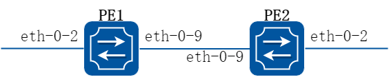
图19-4配置VPWS拓扑
使用LDP配置VPWS
本章VPWS基于LDP,标准为IETF的[L2TRANS]。
以下配置如未说明在哪个Switch配置,则表示所有Switch配置相同:
步骤 1进入配置模式
Switch# configure terminal
步骤 2进入接口配置模式,配置接口属性
PE1的接口配置:
PE1(config)# interface eth-0-2
PE1(config-if)# mpls-l2-circuit t1 ethernet
PE1(config-if)# exit
PE1(config)# interface loopback 0
PE1(config-if)# ip address 192.168.10.10/32
PE1(config-if)# exit
PE1(config)# interface eth-0-9
PE1(config-if)# no switchport
PE1(config-if)# ip address 8.8.8.1/24
PE1(config-if)# enable-ldp
PE1(config-if)# label-switching
PE1(config-if)# exit
PE2的接口配置:
PE2(config)# interface eth-0-2
PE2(config-if)# mpls-l2-circuit t1 ethernet
PE2(config-if)# exit
PE2(config)# interface loopback 0
PE2(config-if)# ip address 192.168.11.10/32
PE2(config-if)# exit
PE2(config)# interface eth-0-9
PE2(config-if)# no switchport
PE2(config-if)# ip address 8.8.8.2/24
PE2(config-if)# enable-ldp
PE2(config-if)# label-switching
PE2(config-if)# exit
步骤 3使能ldp路由
PE1的LDP配置:
PE1(config)# router ldp
PE1(config-router)# router-id 192.168.10.10
PE1(config-router)# targeted-peer 192.168.11.10
PE1(config-router)# exit
PE2的LDP配置:
PE2(config)# router ldp
PE2(config-router)# router-id 192.168.11.10
PE2(config-router)# targeted-peer 192.168.10.10
PE2(config-router)# exit
步骤 4配置VPWS VC ID
PE1的VC ID配置:
PE1(config)# mpls l2-circuit t1 200 192.168.11.10 raw
PE2的VC ID配置:
PE2(config)# mpls l2-circuit t1 200 192.168.10.10 raw
步骤 5使能rip路由
Switch(config)# router rip
Switch(config-router)# network 0.0.0.0/0
Switch(config-router)# exit
步骤 6退出配置模式
Switch(config)# end
步骤 7命令验证
使用show mpls l2-circuit和show mpls vc-table来显示VPWS的相关信息。
PE1显示结果:
PE1# show mpls l2-circuit
VC-Name VC-ID Interface AC-type VLAN PW-mode Manual
t1 200 eth-0-2 Ethernet N/A Raw No
PE1# show mpls vc-table
VC-ID PW Intf AC Intf L/R Label EndPoint Status Manual
200 eth-0-9 eth-0-2 32768/32768 192.168.11.10 Active No
PE2显示结果:
PE2# show mpls l2-circuit
VC-Name VC-ID Interface AC-type VLAN PW-mode Manual
t1 200 eth-0-2 Ethernet N/A Raw No
PE2# show mpls vc-table
VC-ID PW Intf AC Intf L/R Label EndPoint Status Manual
200 eth-0-9 eth-0-2 32768/32768 192.168.10.10 Active No
配置静态VPWS
下面的例子描述了如何配置静态VPWS。
以下配置如未说明在哪个Switch配置,则表示所有Switch配置相同:
步骤 1进入配置模式
Switch# configure terminal
步骤 2进入接口配置模式,配置接口属性
PE1的接口配置:
PE1(config)# interface eth-0-2
PE1(config-if)# mpls-l2-circuit t2 ethernet
PE1(config-if)# exit
PE1(config)# interface loopback 0
PE1(config-if)# ip address 192.168.10.10/32
PE1(config-if)# exit
PE1(config)# interface eth-0-9
PE1(config-if)# no switchport
PE1(config-if)# ip address 8.8.8.1/24
PE1(config-if)# label-switching
PE1(config-if)# exit
PE2的接口配置:
PE2(config)# interface eth-0-2
PE2(config-if)# mpls-l2-circuit t2 ethernet
PE2(config-if)# exit
PE2(config)# interface loopback 0
PE2(config-if)# ip address 192.168.11.10/32
PE2(config-if)# exit
PE2(config)# interface eth-0-9
PE2(config-if)# no switchport
PE2(config-if)# ip address 8.8.8.2/24
PE2(config-if)# label-switching
PE2(config-if)# exit
步骤 3配置ftn条目
PE1的FTN条目:
PE1(config)# mpls ftn-entry 192.168.11.1/24 111 8.8.8.2
PE2的FTN条目:
PE2(config)# mpls ftn-entry 192.168.10.1/24 222 8.8.8.1
步骤 4配置静态ilm
PE1的静态ilm:
PE1(config)# mpls ilm-entry pop 212
PE2的静态ilm:
PE2(config)# mpls ilm-entry pop 111
步骤 5配置VPWS VC ID
PE1的VC ID配置:
PE1(config)# mpls l2-circuit t2 201 192.168.11.10 raw manual
PE1(config)# mpls l2-circuit-fib-entry t2 44 33
PE2的VC ID配置:
PE2(config)# mpls l2-circuit t2 201 192.168.10.10 raw manual
PE2(config)# mpls l2-circuit-fib-entry t2 33 44
步骤 6退出配置模式
Switch(config)# end
步骤 7命令验证
使用show mpls l2-circuit和show mpls vc-table来显示VPWS的相关信息。
PE1显示结果:
PE1# show mpls l2-circuit
VC-Name VC-ID Interface AC-type VLAN PW-mode Manual
t2 201 eth-0-2 Ethernet N/A Raw Yes
PE1# show mpls vc-table
VC-ID PW Intf AC Intf L/R Label EndPoint Status Manual
201 eth-0-9 eth-0-2 44/33 192.168.11.10 Active Yes
PE2显示结果:
PE2# show mpls l2-circuit
VC-Name VC-ID Interface AC-type VLAN PW-mode Manual
t2 201 eth-0-2 Ethernet N/A Raw Yes
PE2# show mpls vc-table
VC-ID PW Intf AC Intf L/R Label EndPoint Status Manual
201 eth-0-9 eth-0-2 33/44 192.168.10.10 Active Yes
配置VPWS透传二层协议报文
下面的例子描述了如何配置VPWS透传二层协议报文。
以下配置如未说明在哪个Switch配置,则表示所有Switch配置相同:
步骤 1进入配置模式
Switch# configure terminal
步骤 2全局使能L2 protocol
Switch(config)# l2protocol enable
步骤 3进入接口配置模式,配置接口属性
PE1的接口配置:
PE1(config)# interface eth-0-2
PE1(config-if)# mpls-l2-circuit t1 ethernet
PE1(config-if)# l2protocol stp tunnel
PE1(config-if)# exit
PE1(config)# interface loopback 0
PE1(config-if)# ip address 192.168.10.10/32
PE1(config-if)# exit
PE1(config)# interface eth-0-9
PE1(config-if)# no switchport
PE1(config-if)# ip address 8.8.8.1/24
PE1(config-if)# enable-ldp
PE1(config-if)# label-switching
PE1(config-if)# exit
PE2的接口配置:
PE2(config)# l2protocol enable
PE2(config)# interface eth-0-2
PE2(config-if)# mpls-l2-circuit t1 ethernet
PE2(config-if)# l2protocol stp tunnel
PE2(config-if)# exit
PE2(config)# interface loopback 0
PE2(config-if)# ip address 192.168.11.10/32
PE2(config-if)# exit
PE2(config)# interface eth-0-9
PE2(config-if)# no switchport
PE2(config-if)# ip address 8.8.8.2/24
PE2(config-if)# enable-ldp
PE2(config-if)# label-switching
PE2(config-if)# exit
步骤 4使能ldp路由
PE1的LDP配置:
PE1(config)# router ldp
PE1(config-router)# router-id 192.168.10.10
PE1(config-router)# targeted-peer 192.168.11.10
PE1(config-router)# exit
PE2的LDP配置:
PE2(config)# router ldp
PE2(config-router)# router-id 192.168.11.10
PE2(config-router)# targeted-peer 192.168.10.10
PE2(config-router)# exit
步骤 5配置VPWS VC ID
PE1的VC ID配置:
PE1(config)# mpls l2-circuit t1 200 192.168.11.10 raw
PE2的VC ID配置:
PE2(config)# mpls l2-circuit t1 200 192.168.10.10 raw
步骤 6使能rip路由
switch(config)# router rip
switch(config-router)# network 0.0.0.0/0
switch(config-router)# exit
步骤 7退出配置模式
Switch(config)# end
19.5.1概述
简介
MPLS QoS是部署QoS(Quality of Service)业务的重要组成部分,在实际的MPLS组网方案中往往通过差分服务(DiffServ)模型来实施QoS。它可以为每个通过MPLS网络的业务提供指定的服务,并提供差异化的服务类型来满足各种需求。
MPLS使用标签转发替代了传统的路由转发,功能强大、灵活,可以满足各种新应用对网络的要求,而且MPLS支持多种网络协议(如IPv4、IPv6等)。目前MPLS被广泛地应用于大规模网络的组建,而在MPLS网络中,无法通过IP QoS来实现服务质量(QoS),所以在MPLS网络中实现服务质量也就应运而生,即MPLS QoS。
与传统IP QoS根据IP报文的优先级来区分业务的服务等级类似,MPLS QoS根据报文的EXP来区分不同的数据流,实现差分服务,保证语音、视频数据流的低延时、低丢包率,保证网络的高利用率。
原理描述
MPLS隧道模式包含三种模式:Uniform、Pipe、Short Pipe。
Uniform模式:报文在IP网和MPLS网中的优先级标识是统一定义的,即两种网络对报文的优先级标识都是全局有效的。在Ingress上,报文被加上标签,DSCP映射到EXP。如果报文在MPLS网络中改变了EXP字段的值,会影响报文离开MPLS网络后采用的PHB(Per-Hop Behavior)。即在出节点会将EXP映射到DSCP。
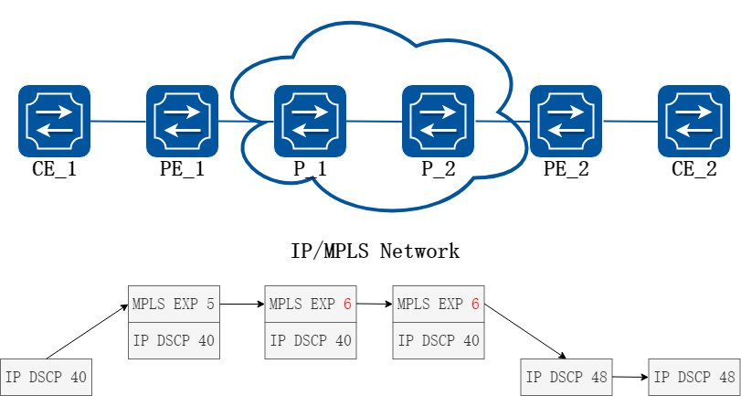
图19-5Uniform模式
Pipe模式:在Ingress上报文压入MPLS标签的EXP值可以由用户指定。如果报文在MPLS网络中改变了EXP字段的值,只在MPLS网络中有效。在Egress上,报文会根据EXP字段的值选择PHB。当报文离开MPLS网络后,报文之前携带的DSCP继续有效。
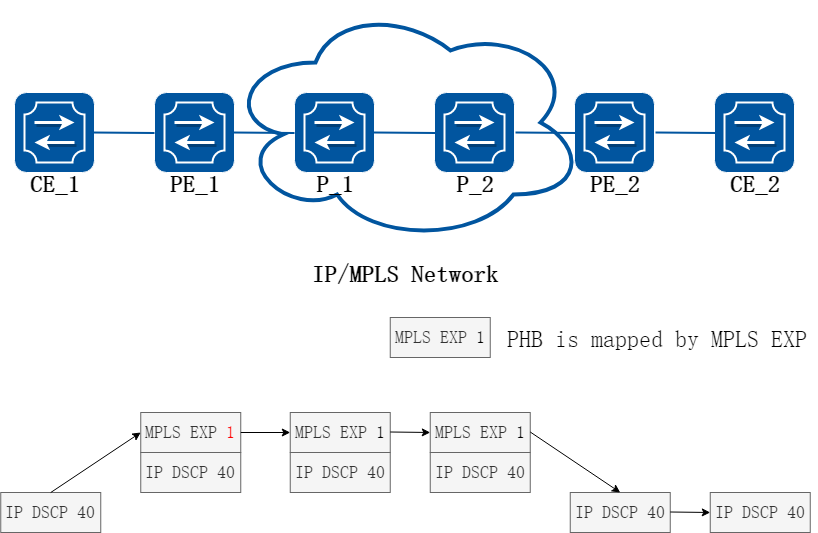
图19-6Pipe模式
Short pipe模式:在Ingress上报文压入MPLS标签的EXP值可以由用户指定。如果报文在MPLS网络中改变了EXP字段的值,只在MPLS网络中有效。在Egress上,报文会根据DSCP选择PHB。当报文离开MPLS网络后,报文之前携带的DSCP继续有效。
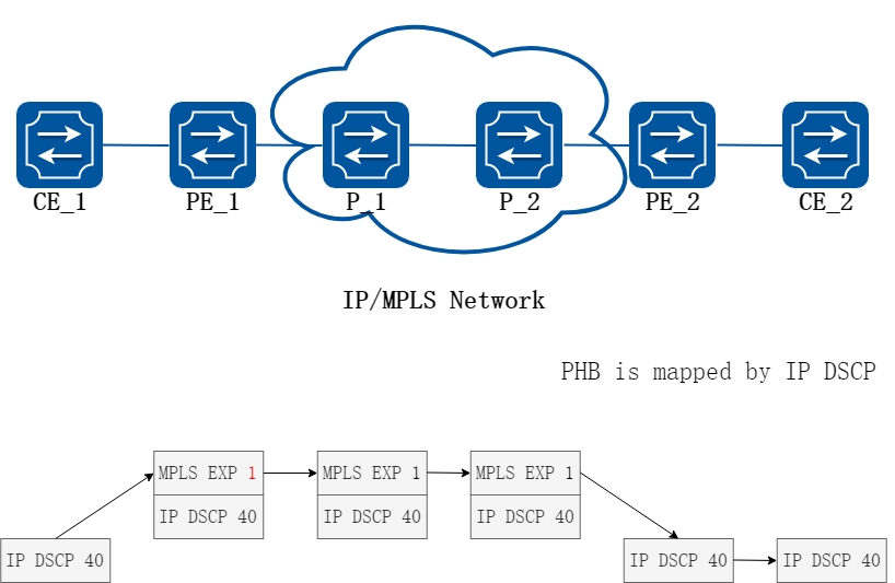
图19-7Short pipe模式
19.5.2配置举例

图19-8MPLS QoS LSP 模型
配置MPLS QoS Uniform
下面的例子描述了如何配置MPLS QoS Uniform模式。
以下配置如未说明在哪个Switch配置,则表示所有Switch配置相同:
步骤 1进入配置模式
Switch# configure terminal
步骤 2配置全局MPLS隧道模式
Switch(config)# mpls lsp-model uniform
步骤 3进入接口配置模式,配置接口属性
PE1的接口配置:
PE1(config)# interface eth-0-9
PE1(config-if)# no switchport
PE1(config-if)# ip address 10.0.9.1/24
PE1(config-if)# label-switching
PE1(config-if)# exit
PE1(config)# interface eth-0-1
PE1(config-if)# no switchport
PE1(config-if)# qos domain type dscp 1
PE1(config-if)# trust dscp
PE1(config-if)# replace dscp
PE1(config-if)# ip address 1.1.1.1/24
PE1(config-if)# label-switching
PE1(config-if)# exit
P的接口配置:
P(config)# interface eth-0-9
P(config-if)# no switchport
P(config-if)# ip address 10.0.9.2/24
P(config-if)# label-switching
P(config-if)# exit
P(config)# interface eth-0-17
P(config-if)# no switchport
P(config-if)# ip address 10.0.17.2/24
P(config-if)# label-switching
P(config-if)# exit
PE2的接口配置:
PE2(config)# interface eth-0-17
PE2(config-if)# no switchport
PE2(config-if)# ip address 10.0.17.1/24
PE2(config-if)# label-switching
PE2(config-if)# exit
PE2(config)# interface eth-0-1
PE2(config-if)# no switchport
PE2(config-if)# qos domain type dscp 1
PE2(config-if)# trust dscp
PE2(config-if)# replace dscp
PE2(config-if)# ip address 2.2.2.2/24
PE2(config-if)# label-switching
PE2(config-if)# exit
步骤 4配置静态arp
PE1的接口配置:
PE1(config)# arp 1.1.1.2 0001.0001.0002
PE2的接口配置:
PE2(config)# arp 2.2.2.1 0002.0002.0001
步骤 5配置静态ftn/ilm
PE1的静态ftn:
PE1(config)# mpls ftn-entry 2.2.2.0/24 102 10.0.9.2
PE1(config)# mpls ilm-entry pop 201
P的静态ilm:
P(config)# mpls ilm-entry swap 102 10.0.17.1 203
P(config)# mpls ilm-entry swap 302 10.0.9.1 201
PE2的静态ilm:
PE2(config)# mpls ftn-entry 1.1.1.0/24 302 10.0.17.2
PE2(config)# mpls ilm-entry pop 203
步骤 6命令验证
PE1 显示结果:
PE1# show mpls ftn-database
Codes: > - selected FTN, p - stale FTN, B - BGP FTN, K - CLI FTN,
L - LDP FTN, R - RSVP-TE FTN, S - SNMP FTN, I - IGP-Shortcut,
* -bypass FTN, U - unknown FTN
Code FEC Out-Label Nexthop Out-Intf
K> 2.2.2.0/24 102 10.0.9.2 eth-0-9
PE1# show mpls ilm-database
Codes: > - selected ILM, * - LSP ILM, p - stale ILM, B - BGP ILM, K - CLI ILM,
L - LDP ILM, R - RSVP-TE ILM, S - SNMP ILM, I - IGP-Shortcut
U - unknown ILM
Code FEC I/O Label Nexthop Out-Intf
K> 0.0.0.0/0 201/- 0.0.0.0 N/A
P显示结果:
P# show mpls ilm-database
Codes: > - selected ILM, * - LSP ILM, p - stale ILM, B - BGP ILM, K - CLI ILM,
L - LDP ILM, R - RSVP-TE ILM, S - SNMP ILM, I - IGP-Shortcut
U - unknown ILM
Code FEC I/O Label Nexthop Out-Intf
K> 0.0.0.0/0 102/203 10.0.17.1 eth-0-17
K> 0.0.0.0/0 302/201 10.0.9.1 eth-0-9
PE2 显示结果:
PE2# show mpls ftn-database
Codes: > - selected FTN, p - stale FTN, B - BGP FTN, K - CLI FTN,
L - LDP FTN, R - RSVP-TE FTN, S - SNMP FTN, I - IGP-Shortcut,
* -bypass FTN, U - unknown FTN
Code FEC Out-Label Nexthop Out-Intf
K> 1.1.1.0/24 302 10.0.17.2 eth-0-17
PE2# show mpls ilm-database
Codes: > - selected ILM, * - LSP ILM, p - stale ILM, B - BGP ILM, K - CLI ILM,
L - LDP ILM, R - RSVP-TE ILM, S - SNMP ILM, I - IGP-Shortcut
U - unknown ILM
Code FEC I/O Label Nexthop Out-Intf
K> 0.0.0.0/0 203/- 0.0.0.0 N/A
配置MPLS QoS Pipe
下面的例子描述了如何配置MPLS QoS Pipe模式。
以下配置如未说明在哪个Switch配置,则表示所有Switch配置相同:
步骤 1进入配置模式
Switch# configure terminal
步骤 2配置全局MPLS隧道模式
PE1的接口配置:
PE1(config)# mpls lsp-model pipe exp 7
P的接口配置:
P(config)# mpls lsp-model pipe
PE2的接口配置:
PE2(config)# mpls lsp-model pipe exp 7
步骤 3进入接口配置模式,配置接口属性
PE1的接口配置:
PE1(config)# interface eth-0-9
PE1(config-if)# no switchport
PE1(config-if)# ip address 10.0.9.1/24
PE1(config-if)# label-switching
PE1(config-if)# exit
PE1(config)# interface eth-0-1
PE1(config-if)# no switchport
PE1(config-if)# qos domain type dscp 1
PE1(config-if)# trust dscp
PE1(config-if)# ip address 1.1.1.1/24
PE1(config-if)# label-switching
PE1(config-if)# exit
P的接口配置:
P(config)# interface eth-0-9
P(config-if)# no switchport
P(config-if)# ip address 10.0.9.2/24
P(config-if)# label-switching
P(config-if)# exit
P(config)# interface eth-0-17
P(config-if)# no switchport
P(config-if)# ip address 10.0.17.2/24
P(config-if)# label-switching
P(config-if)# exit
PE2的接口配置:
PE2(config)# interface eth-0-17
PE2(config-if)# no switchport
PE2(config-if)# ip address 10.0.17.1/24
PE2(config-if)# label-switching
PE2(config-if)# exit
PE2(config)# interface eth-0-1
PE2(config-if)# no switchport
PE2(config-if)# qos domain type dscp 1
PE2(config-if)# trust dscp
PE2(config-if)# ip address 2.2.2.2/24
PE2(config-if)# label-switching
PE2(config-if)# exit
步骤 4配置静态arp
PE1的接口配置:
PE1(config)# arp 1.1.1.2 0001.0001.0002
PE2的接口配置:
PE2(config)# arp 2.2.2.1 0002.0002.0001
步骤 5配置静态ftn/ilm
PE1的静态ftn:
PE1(config)# mpls ftn-entry 2.2.2.0/24 102 10.0.9.2
PE1(config)# mpls ilm-entry pop 201
P的静态ilm:
P(config)# mpls ilm-entry swap 102 10.0.17.1 203
P(config)# mpls ilm-entry swap 302 10.0.9.1 201
PE2的静态ilm:
PE2(config)# mpls ftn-entry 1.1.1.0/24 302 10.0.17.2
PE2(config)# mpls ilm-entry pop 203
步骤 6命令验证
PE1 显示结果:
PE1# show mpls ftn-database
Codes: > - selected FTN, p - stale FTN, B - BGP FTN, K - CLI FTN,
L - LDP FTN, R - RSVP-TE FTN, S - SNMP FTN, I - IGP-Shortcut,
* -bypass FTN, U - unknown FTN
Code FEC Out-Label Nexthop Out-Intf
K> 2.2.2.0/24 102 10.0.9.2 eth-0-9
PE1# show mpls ilm-database
Codes: > - selected ILM, * - LSP ILM, p - stale ILM, B - BGP ILM, K - CLI ILM,
L - LDP ILM, R - RSVP-TE ILM, S - SNMP ILM, I - IGP-Shortcut
U - unknown ILM
Code FEC I/O Label Nexthop Out-Intf
K> 0.0.0.0/0 201/- 0.0.0.0 N/A
P显示结果:
P# show mpls ilm-database
Codes: > - selected ILM, * - LSP ILM, p - stale ILM, B - BGP ILM, K - CLI ILM,
L - LDP ILM, R - RSVP-TE ILM, S - SNMP ILM, I - IGP-Shortcut
U - unknown ILM
Code FEC I/O Label Nexthop Out-Intf
K> 0.0.0.0/0 102/203 10.0.17.1 eth-0-17
K> 0.0.0.0/0 302/201 10.0.9.1 eth-0-9
PE2 显示结果:
PE2# show mpls ftn-database
Codes: > - selected FTN, p - stale FTN, B - BGP FTN, K - CLI FTN,
L - LDP FTN, R - RSVP-TE FTN, S - SNMP FTN, I - IGP-Shortcut,
* -bypass FTN, U - unknown FTN
Code FEC Out-Label Nexthop Out-Intf
K> 1.1.1.0/24 302 10.0.17.2 eth-0-17
PE2# show mpls ilm-database
Codes: > - selected ILM, * - LSP ILM, p - stale ILM, B - BGP ILM, K - CLI ILM,
L - LDP ILM, R - RSVP-TE ILM, S - SNMP ILM, I - IGP-Shortcut
U - unknown ILM
Code FEC I/O Label Nexthop Out-Intf
K> 0.0.0.0/0 203/- 0.0.0.0 N/A
配置MPLS QoS Short Pipe
下面的例子描述了如何配置MPLS QoS Short Pipe模式。
以下配置如未说明在哪个Switch配置,则表示所有Switch配置相同:
步骤 1进入配置模式
Switch# configure terminal
步骤 2配置全局MPLS隧道模式
PE1的接口配置:
PE1(config)# mpls lsp-model short-pipe exp 7
P的接口配置:
P(config)# mpls lsp-model short-pipe
PE2的接口配置:
PE2(config)# mpls lsp-model short-pipe exp 7
步骤 3进入接口配置模式,配置接口属性
PE1的接口配置:
PE1(config)# interface eth-0-9
PE1(config-if)# no switchport
PE1(config-if)# ip address 10.0.9.1/24
PE1(config-if)# label-switching
PE1(config-if)# exit
PE1(config)# interface eth-0-1
PE1(config-if)# no switchport
PE1(config-if)# qos domain type dscp 1
PE1(config-if)# trust dscp
PE1(config-if)# ip address 1.1.1.1/24
PE1(config-if)# label-switching
PE1(config-if)# exit
P的接口配置:
P(config)# interface eth-0-9
P(config-if)# no switchport
P(config-if)# ip address 10.0.9.2/24
P(config-if)# label-switching
P(config-if)# exit
P(config)# interface eth-0-17
P(config-if)# no switchport
P(config-if)# ip address 10.0.17.2/24
P(config-if)# label-switching
P(config-if)# exit
PE2的接口配置:
PE2(config)# interface eth-0-17
PE2(config-if)# no switchport
PE2(config-if)# ip address 10.0.17.1/24
PE2(config-if)# label-switching
PE2(config-if)# exit
PE2(config)# interface eth-0-1
PE2(config-if)# no switchport
PE2(config-if)# qos domain type dscp 1
PE2(config-if)# trust dscp
PE2(config-if)# ip address 2.2.2.2/24
PE2(config-if)# label-switching
PE2(config-if)# exit
步骤 4配置静态arp
PE1的接口配置:
PE1(config)# arp 1.1.1.2 0001.0001.0002
PE2的接口配置:
PE2(config)# arp 2.2.2.1 0002.0002.0001
步骤 5配置静态ftn/ilm
PE1的静态ftn:
PE1(config)# mpls ftn-entry 2.2.2.0/24 102 10.0.9.2
PE1(config)# mpls ilm-entry pop 201
P的静态ilm:
P(config)# mpls ilm-entry swap 102 10.0.17.1 203
P(config)# mpls ilm-entry swap 302 10.0.9.1 201
PE2的静态ilm:
PE2(config)# mpls ftn-entry 1.1.1.0/24 302 10.0.17.2
PE2(config)# mpls ilm-entry pop 203
步骤 6命令验证
PE1 显示结果:
PE1# show mpls ftn-database
Codes: > - selected FTN, p - stale FTN, B - BGP FTN, K - CLI FTN,
L - LDP FTN, R - RSVP-TE FTN, S - SNMP FTN, I - IGP-Shortcut,
* -bypass FTN, U - unknown FTN
Code FEC Out-Label Nexthop Out-Intf
K> 2.2.2.0/24 102 10.0.9.2 eth-0-9
PE1# show mpls ilm-database
Codes: > - selected ILM, * - LSP ILM, p - stale ILM, B - BGP ILM, K - CLI ILM,
L - LDP ILM, R - RSVP-TE ILM, S - SNMP ILM, I - IGP-Shortcut
U - unknown ILM
Code FEC I/O Label Nexthop Out-Intf
K> 0.0.0.0/0 201/- 0.0.0.0 N/A
P显示结果:
P# show mpls ilm-database
Codes: > - selected ILM, * - LSP ILM, p - stale ILM, B - BGP ILM, K - CLI ILM,
L - LDP ILM, R - RSVP-TE ILM, S - SNMP ILM, I - IGP-Shortcut
U - unknown ILM
Code FEC I/O Label Nexthop Out-Intf
K> 0.0.0.0/0 102/203 10.0.17.1 eth-0-17
K> 0.0.0.0/0 302/201 10.0.9.1 eth-0-9
PE2 显示结果:
PE2# show mpls ftn-database
Codes: > - selected FTN, p - stale FTN, B - BGP FTN, K - CLI FTN,
L - LDP FTN, R - RSVP-TE FTN, S - SNMP FTN, I - IGP-Shortcut,
* -bypass FTN, U - unknown FTN
Code FEC Out-Label Nexthop Out-Intf
K> 1.1.1.0/24 302 10.0.17.2 eth-0-17
PE2# show mpls ilm-database
Codes: > - selected ILM, * - LSP ILM, p - stale ILM, B - BGP ILM, K - CLI ILM,
L - LDP ILM, R - RSVP-TE ILM, S - SNMP ILM, I - IGP-Shortcut
U - unknown ILM
Code FEC I/O Label Nexthop Out-Intf
K> 0.0.0.0/0 203/- 0.0.0.0 N/A
19.6.1概述
简介
本章节描述了如何配置L3VPN。其核心思想是通过Route Target的export和import属性控制路由在VRF间的收发,通过RD去区分来自不同VPN的路由,通过内层label去映射出不同的vrf来指导数据的三层转发。
19.6.2配置举例
1.组网拓扑
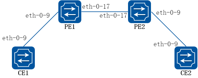
图19-9L3VPN 模型
2.配置步骤
下面的例子描述了如何使用配置L3VPN.
以下配置如未说明在哪个Switch配置,则表示所有Switch配置相同:
步骤 1进入配置模式
Switch# configure terminal
步骤 2vrf配置
PE1的vrf配置:
PE1(config)# ip vrf vpn1
PE1(config-vrf)# rd 1:1
PE1(config-vrf)# route-target both 1:1
PE1(config-vrf)# exit
PE2的vrf配置:
PE2(config)# ip vrf vpn1
PE2(config-vrf)# rd 1:1
PE2(config-vrf)# route-target both 1:1
PE2(config-vrf)# exit
步骤 3进入接口配置模式,配置接口属性
CE1的接口配置:
CE1(config)# interface eth-0-9
CE1(config-if)# no switchport
CE1(config-if)# ip address 2.2.2.1/24
CE1(config-if)# exit
CE1(config)# interface loopback 0
CE1(config-if)# ip address 4.4.4.4/32
CE1(config-if)# exit
PE1的接口配置,eth-0-9需要使能ldp并且加入vrf:
PE1(config)# interface eth-0-9
PE1(config-if)# no switchport
PE1(config-if)# ip vrf forwarding vpn1
PE1(config-if)# ip address 2.2.2.2/24
PE1(config-if)# exit
PE1(config)# interface eth-0-17
PE1(config-if)# no switchport
PE1(config-if)# label-switching
PE1(config-if)# ip address 1.1.1.1/24
PE1(config-if)# enable-ldp
PE1(config-if)# exit
PE1(config)# interface loopback 0
PE1(config-if)# ip address 5.5.5.5/32
PE1(config-if)# exit
PE2的接口配置,eth-0-9需要使能ldp并且加入vrf:
PE2(config)# interface eth-0-9
PE2(config-if)# no switchport
PE2(config-if)# ip vrf forwarding vpn1
PE2(config-if)# ip address 3.3.3.3/24
PE2(config-if)# exit
PE2(config)# interface eth-0-17
PE2(config-if)# no switchport
PE2(config-if)# label-switching
PE2(config-if)# ip address 1.1.1.2/24
PE2(config-if)# enable-ldp
PE2(config-if)# exit
PE2(config)# interface loopback 0
PE2(config-if)# ip address 6.6.6.6/32
PE2(config-if)# exit
CE2的接口配置:
CE2(config)# interface eth-0-9
CE2(config-if)# no switchport
CE2(config-if)# ip address 3.3.3.4/24
CE2(config-if)# exit
CE2(config)# interface loopback0
CE2(config-if)# ip address 7.7.7.7/32
CE2(config-if)# exit
步骤 4使能ldp路由
PE1的LDP配置:
PE1(config)# router ldp
PE1(config-router)# router-id 5.5.5.5
PE1(config-router)# exit
PE2的LDP配置:
PE2(config)# router ldp
PE2(config-router)# router-id 6.6.6.6
PE2(config-router)# exit
步骤 5使能rip路由
CE1的RIP配置:
CE1(config)# router rip
CE1(config-router)# network 2.2.2.2/24
CE1(config-router)# redistribute connected
CE1(config-router)# exit
PE1的RIP配置:
PE1(config)# router rip
PE1(config-router)# address-family ipv4 vrf vpn1
PE1(config-router-af)# network 2.2.2.0/24
PE1(config-router-af)# redistribute bgp
PE1(config-router-af)# exit-address-family
PE1(config-router)# exit
PE2的RIP配置:
PE2(config)# router rip
PE2(config-router)# address-family ipv4 vrf vpn1
PE2(config-router-af)# network 3.3.3.3/24
PE2(config-router-af)# redistribute bgp
PE2(config-router-af)# exit-address-family
PE2(config-router)# exit
CE2的RIP配置:
CE2(config)# router rip
CE2(config-router)# network 3.3.3.0/24
CE2(config-router)# redistribute connected
CE2(config-router)# exit
步骤 6使能ospf路由f
PE1的OSPF配置:
PE1(config)#router ospf
PE1(config-router)# redistribute connected
PE1(config-router)# network 1.1.1.0/24 area 0
PE1(config-router)# exit
PE2的OSPF配置:
PE2(config)# router ospf
PE2(config-router)# redistribute connected
PE2(config-router)# network 1.1.1.0/24 area 0
PE2(config-router)# exit
步骤 7使能bgp路由
PE1的BGP配置:
PE1(config)# router bgp 1
PE1(config-router)# neighbor 6.6.6.6 remote-as 1
PE1(config-router)# neighbor 6.6.6.6 update-source loopback0
PE1(config-router)# address-family ipv4
PE1(config-router-af)# no synchronization
PE1(config-router-af)# neighbor 6.6.6.6 activate
PE1(config-router-af)# exit-address-family
PE1(config-router)# address-family vpnv4 unicast
PE1(config-router-af)# no synchronization
PE1(config-router-af)# neighbor 6.6.6.6 activate
PE1(config-router-af)# neighbor 6.6.6.6 send-community both
PE1(config-router-af)# exit-address-family
PE1(config-router)# address-family ipv4 vrf vpn1
PE1(config-router-af)# redistribute connected
PE1(config-router-af)# redistribute rip
PE1(config-router-af)# no synchronization
PE1(config-router-af)# exit-address-family
PE1(config-router)# exit
PE2的BGP配置:
PE2(config)# router bgp 1
PE2(config-router)# neighbor 5.5.5.5 remote-as 1
PE2(config-router)# neighbor 5.5.5.5 update-source loopback0
PE2(config-router)# address-family ipv4
PE2(config-router-af)# no synchronization
PE2(config-router-af)# neighbor 5.5.5.5 activate
PE2(config-router-af)# exit-address-family
PE2(config-router)# address-family vpnv4 unicast
PE2(config-router-af)# no synchronization
PE2(config-router-af)# neighbor 5.5.5.5 activate
PE2(config-router-af)# neighbor 5.5.5.5 send-community both
PE2(config-router-af)# exit-address-family
PE2(config-router)# address-family ipv4 vrf vpn1
PE2(config-router-af)# redistribute connected
PE2(config-router-af)# redistribute rip
PE2(config-router-af)# no synchronization
PE2(config-router-af)# exit-address-family
PE2(config-router)# exit
步骤 8命令验证
通过在CE1上show ip route和ping CE2 loopback地址来验证L3VPN的可达性。
PE1显示结果:
PE1# show ip route
s: K - kernel, C - connected, S - static, R - RIP, B - BGP
O - OSPF, IA - OSPF inter area
N1 - OSPF NSSA external type 1, N2 - OSPF NSSA external type 2
E1 - OSPF external type 1, E2 - OSPF external type 2
i - IS-IS, L1 - IS-IS level-1, L2 - IS-IS level-2, ia - IS-IS inter area
Dc - DHCP Client
[*] - [AD/Metric]
* - candidate default
C 2.2.2.0/24 is directly connected, eth-0-9
C 2.2.2.1/32 is in local loopback, eth-0-9
R 3.3.3.0/24 [120/2] via 2.2.2.2, eth-0-9, 00:00:04
C 4.4.4.4/32 is directly connected, loopback0
R 7.7.7.7/32 [120/2] via 2.2.2.2, eth-0-9, 00:00:02
PE1# ping 7.7.7.7
PING 7.7.7.7 (7.7.7.7) 56(84) bytes of data.
64 bytes from 7.7.7.7: icmp_seq=0 ttl=62 time=1828 ms
64 bytes from 7.7.7.7: icmp_seq=1 ttl=62 time=1801 ms
64 bytes from 7.7.7.7: icmp_seq=2 ttl=62 time=1775 ms
64 bytes from 7.7.7.7: icmp_seq=3 ttl=62 time=1775 ms
64 bytes from 7.7.7.7: icmp_seq=4 ttl=62 time=1705 ms
--- 7.7.7.7 ping statistics ---
5 packets transmitted, 5 received, 0% packet loss, time 4018ms
rtt min/avg/max/mdev = 1705.600/1777.267/1828.148/40.840 ms, pipe 3
19.7.1概述
简介
SR(Segment Routing,分段路由)采用源路径选择机制,预先在源节点封装好路径所要经过节点分配的SID(Segment Identifier,段标识),当报文经过SR 节点时,该节点根据报文的SID 对报文进行转发。除源节点外,其它节点无需维护路径状态。MPLS SR(Segment Routing with MPLS,MPLS 段路由)是指在MPLS 网络中使用SR、将标签作为SID 对报文进行转发。
原理描述
要想通过 SR LSP 转发报文,需要完成以下工作:
• 进行标签分配,为报文转发路径中的每个节点和链路规划标签信息,可以使用静态配置Segment或者动态分配SID两种方式。
• 建立标签转发表项,运行MPLS SR 的设备组成的分段路由域内的设备根据分配的标签信息形成本地的标签转发表项。
• 建立SR LSP,SR LSP 可以手工配置,也可以通过控制器动态创建。
• 将SR隧道和SR LSP 关联,以便SR隧道采用SR LSP 进行报文转发。
完成上述步骤后,当源节点接收到用户网络的报文后,会为报文封装所经过路径上的标签信息,并通过SR LSP 将报文转发给尾节点;尾节点从SR LSP 接收到报文后,会剥离报文中的标签,根据原始报文的目的地址查找路由表进行报文转发。
19.7.2配置举例
配置静态MPLS SR
1.组网拓扑
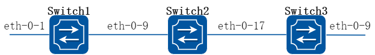
图19-10MPLS SR拓扑
2.配置步骤
下面的例子描述了如何配置静态MPLS SR。
步骤 1进入配置模式
Switch# configure terminal
步骤 2进入接口配置模式,配置接口属性
Switch1上的接口配置:
Switch1(config)# interface eth-0-1
Switch1(config-if)# no switchport
Switch1(config-if)# no shutdown
Switch1(config-if)# ip address 1.1.1.1/24
Switch1(config-if)# exit
Switch1(config)# interface eth-0-9
Switch1(config-if)# no switchport
Switch1(config-if)# no shutdown
Switch1(config-if)# ip address 12.1.1.1/24
Switch1(config-if)# label-switching
Switch1(config-if)# exit
Switch2上的接口配置:
Switch2(config)# interface eth-0-9
Switch2(config-if)# no switchport
Switch2(config-if)# no shutdown
Switch2(config-if)# ip address 12.1.1.2/24
Switch2(config-if)# label-switching
Switch2(config-if)# exit
Switch2(config)# interface eth-0-17
Switch2(config-if)# no switchport
Switch2(config-if)# no shutdown
Switch2(config-if)# ip address 23.1.1.2/24
Switch2(config-if)# label-switching
Switch2(config-if)# exit
Switch3上的接口配置:
Switch3(config)# interface eth-0-17
Switch3(config-if)# no switchport
Switch3(config-if)# no shutdown
Switch3(config-if)# ip address 23.1.1.3/24
Switch3(config-if)# label-switching
Switch3(config-if)# exit
Switch3(config)# interface eth-0-9
Switch3(config-if)# no switchport
Switch3(config-if)# no shutdown
Switch3(config-if)# ip address 34.1.1.3/24
Switch3(config-if)# label-switching
Switch3(config-if)# exit
Switch3(config)# interface loopback0
Switch3(config-if)# ip address 5.5.5.5/32
Switch3(config-if)# exit
步骤 3配置静态路由
Switch2上静态路由的配置:
Switch2(config)# ip route 5.5.5.5/32 23.1.1.3
Switch3上静态路由和静态arp的配置:
Switch3(config)# arp 34.1.1.4 0000.0000.000a
Switch3(config)# ip route 10.10.10.10/32 34.1.1.4
步骤 4静态配置Segment
Switch1上adj segment的配置:
Switch1(config)# static-sr-mpls adjacency adj1 in-label 20 nexthop 12.1.1.2
Switch2上prefix segment的配置:
Switch2(config)# static-sr-mpls prefix prefix1 destination 5.5.5.5/32 in-label 30 nexthop 23.1.1.3 out-label 30
Switch3上prefix segment的配置:
Switch3(config)# static-sr-mpls prefix prefix1 destination 5.5.5.5/32 in-label 30
步骤 5配置SR LSP
Switch1上sr lsp的配置:
Switch1(config)# static-sr-mpls lsp lsp1 out-label 20 30
步骤 6配置SR隧道,绑定SR LSP,再将路由引入该TUNNEL
Switch1上sr tunnel的配置:
Switch1(config)# static-sr-mpls tunnel tun1 non-aps
Switch1(config-sr-tunnel)# primary lsp1
Switch1(config-sr-tunnel)# map-route 10.10.10.10/32
Switch1(config-sr-tunnel)# exit
步骤 7命令验证
显示Switch1上的adj segment表项:
Switch1# show mpls sr-adj
sr-adj id inlabel nexthop lsp_list
adj1 0 20 12.1.1.2 lsp1
显示Switch2上的prefix segment表项:
Switch2# show mpls sr-prefix
sr-prefix id inlabel outlabel nexthop lsp_list
prefix1 0 30 30 23.1.1.3
显示Switch3上的prefix segment表项:
Switch3# show mpls sr-prefix
sr-prefix id inlabel outlabel nexthop lsp_list
prefix1 0 30 1048576 0.0.0.0
显示Switch1上的sr lsp表项:
Switch1# show mpls sr-lsp
sr-lsp id tunid instl nexthop tunnel adj prefix outlabel
lsp1 2 2 1 12.1.1.2 tun1 adj1 - 20 30
显示Switch1上的sr tunnel表项:
Switch1# show mpls sr-tunnel
sr-tunnel id type wlsp plsp slsp map-route
tun1 3 non lsp1 - - 10.10.10.10/32
显示Switch1上的map-route表项:
Switch1# show mpls sr-mapped-routes
Mapped-route SR Tunnel name
10.10.10.10/32 tun1
向Switch1的eth-0-1口发送目的ip地址是10.10.10.10的报文:
在Switch1的eth-0-1口抓收到的报文:
07:45:48.915852 00:00:00:00:00:02 (oui Ethernet) > 22:92:11:2e:47:00 (oui Unknown), ethertype IPv4 (0x0800), length 64: (tos 0x0, ttl 10, id 0, offset 0, flags [none], proto UDP (17), length 50)
1.1.1.3.43690 > 10.10.10.10.43741: [bad udp cksum 0xaadd -> 0x9331!] UDP, length 43682
0x0000: 2292 112e 4700 0000 0000 0002 0800 4500
0x0010: 0032 0000 0000 0a11 9aa4 0101 0103 0a0a
0x0020: 0a0a aaaa aadd aaaa aadd aaaa aadd aaaa
0x0030: aadd aaaa aadd aaaa aadd aaaa aadd aaaa
在Switch1的eth-0-9口抓发出的报文:
07:49:41.883130 22:92:11:2e:47:00 (oui Unknown) > 2c:ad:5e:70:52:00 (oui Unknown), ethertype MPLS unicast (0x8847), length 68: MPLS (label 30, exp 0, [S], ttl 8)
(tos 0x0, ttl 9, id 0, offset 0, flags [none], proto UDP (17), length 50)
1.1.1.3.43690 > 10.10.10.10.43741: [bad udp cksum 0xaadd -> 0x9331!] UDP, length 43682
0x0000: 2cad 5e70 5200 2292 112e 4700 8847 0001
0x0010: e108 4500 0032 0000 0000 0911 9ba4 0101
0x0020: 0103 0a0a 0a0a aaaa aadd aaaa aadd aaaa
0x0030: aadd aaaa aadd aaaa aadd aaaa aadd aaaa
0x0040: aadd aaaa
在Switch2的eth-0-17口抓发出的报文:
07:51:36.664252 2c:ad:5e:70:52:00 (oui Unknown) > 4e:1d:de:29:f9:00 (oui Unknown), ethertype MPLS unicast (0x8847), length 68: MPLS (label 30, exp 0, [S], ttl 7)
(tos 0x0, ttl 9, id 0, offset 0, flags [none], proto UDP (17), length 50)
1.1.1.3.43690 > 10.10.10.10.43741: [bad udp cksum 0xaadd -> 0x9331!] UDP, length 43682
0x0000: 4e1d de29 f900 2cad 5e70 5200 8847 0001
0x0010: e107 4500 0032 0000 0000 0911 9ba4 0101
0x0020: 0103 0a0a 0a0a aaaa aadd aaaa aadd aaaa
0x0030: aadd aaaa aadd aaaa aadd aaaa aadd aaaa
0x0040: aadd aaaa
在Switch3的eth-0-9口抓发出的报文:
07:55:33.886746 4e:1d:de:29:f9:00 (oui Unknown) > 00:00:00:00:00:0a (oui Ethernet), ethertype IPv4 (0x0800), length 64: (tos 0x0, ttl 6, id 0, offset 0, flags [none], proto UDP (17), length 50)
1.1.1.3.43690 > 10.10.10.10.43741: [bad udp cksum 0xaadd -> 0x9331!] UDP, length 43682
0x0000: 0000 0000 000a 4e1d de29 f900 0800 4500
0x0010: 0032 0000 0000 0611 9ea4 0101 0103 0a0a
0x0020: 0a0a aaaa aadd aaaa aadd aaaa aadd aaaa
0x0030: aadd aaaa aadd aaaa aadd aaaa aadd aaaa
配置动态ISIS SR
1.组网拓扑

图19-11MPLS SR拓扑
2.配置步骤
下面的例子描述了如何配置动态ISIS SR。
步骤 1进入配置模式
Switch# configure terminal
步骤 2进入接口配置模式,配置接口属性,并且在各接口上使能isis
Switch1上的接口配置:
Switch1(config)# interface eth-0-1
Switch1(config-if)# no switchport
Switch1(config-if)# no shutdown
Switch1(config-if)# ip address 10.1.1.1/24
Switch1(config-if)# exit
Switch1(config)# interface eth-0-9
Switch1(config-if)# no switchport
Switch1(config-if)# no shutdown
Switch1(config-if)# ip address 12.1.1.1/24
Switch1(config-if)# label-switching
Switch1(config-if)# ip router isis
Switch1(config-if)# exit
Switch1(config)# interface loopback0
Switch1(config-if)# ip address 1.1.1.1/32
Switch1(config-if)# ip router isis
Switch1(config-if)# exit
Switch2上的接口配置:
Switch2(config)# interface eth-0-9
Switch2(config-if)# no switchport
Switch2(config-if)# no shutdown
Switch2(config-if)# ip address 12.1.1.2/24
Switch2(config-if)# label-switching
Switch2(config-if)# ip router isis
Switch2(config-if)# exit
Switch2(config)# interface eth-0-17
Switch2(config-if)# no switchport
Switch2(config-if)# no shutdown
Switch2(config-if)# ip address 23.1.1.2/24
Switch2(config-if)# label-switching
Switch2(config-if)# ip router isis
Switch2(config-if)# exit
Switch2(config)# interface loopback0
Switch2(config-if)# ip address 2.2.2.2/32
Switch2(config-if)# ip router isis
Switch2(config-if)# exit
Switch3上的接口配置:
Switch3(config)# interface eth-0-17
Switch3(config-if)# no switchport
Switch3(config-if)# no shutdown
Switch3(config-if)# ip address 23.1.1.3/24
Switch3(config-if)# label-switching
Switch3(config-if)# ip router isis
Switch3(config-if)# exit
Switch3(config)# interface eth-0-9
Switch3(config-if)# no switchport
Switch3(config-if)# no shutdown
Switch3(config-if)# ip address 34.1.1.3/24
Switch3(config-if)# label-switching
Switch3(config-if)# ip router isis
Switch3(config-if)# exit
Switch3(config)# interface loopback0
Switch3(config-if)# ip address 3.3.3.3/32
Switch3(config-if)# ip router isis
Switch3(config-if)# exit
Switch3(config)# arp 34.1.1.4 0000.0000.000a
Switch3(config)# ip route 5.5.5.5/32 34.1.1.4
步骤 3使能isis路由协议并使能SR
Switch1上的配置:
Switch1(config)# router isis
Switch1(config)# metric-style wide
Switch1(config)# segment-routing mpls
Switch1(config)# segment-routing global-block 16000 16999
Switch1(config)# net 49.0000.0000.0001.00
Switch1(config)# exit
Switch2上的配置:
Switch2(config)# router isis
Switch2(config)# metric-style wide
Switch2(config)# segment-routing mpls
Switch2(config)# segment-routing global-block 17000 17999
Switch2(config)# net 49.0000.0000.0002.00
Switch2(config)# exit
Switch3上的配置:
Switch3(config)# router isis
Switch3(config)# metric-style wide
Switch3(config)# segment-routing mpls
Switch3(config)# segment-routing global-block 18000 18999
Switch3(config)# net 49.0000.0000.0003.00
Switch3(config)# exit
步骤 4配置各设备的前缀SID
Switch1上的配置:
Switch1(config)# interface loopback0
Switch1(config-if)# isis prefix-sid index 10
Switch1(config-if)# exit
Switch2上的配置:
Switch2(config)# interface loopback0
Switch2(config-if)# isis prefix-sid index 20
Switch2(config-if)# exit
Switch3上的配置:
Switch3(config)# interface loopback0
Switch3(config-if)# isis prefix-sid index 30
Switch3(config-if)# exit
步骤 5配置SR LSP
Switch1上sr lsp的配置:
Switch1(config)# static-sr-mpls lsp lsp1 out-label 16030
步骤 6配置SR隧道,绑定SR LSP,再将路由引入该TUNNEL
Switch1上sr tunnel的配置:
Switch1(config)# static-sr-mpls tunnel tun1 non-aps
Switch1(config-sr-tunnel)# primary lsp1
Switch1(config-sr-tunnel)# map-route 5.5.5.5/32
Switch1(config-sr-tunnel)# exit
步骤 7命令验证
显示Switch1上的isis路由表项:
Switch1# show ip isis route
Codes: C - connected, E - external, L1 - IS-IS level-1, L2 - IS-IS level-2
ia - IS-IS inter area, D - discard, e - external metric
Area (null):
Destination Metric Next-Hop Interface Tag Sid Nflag Eflag Chg
C 1.1.1.1/32 10 -- loopback0 0 10 Y N N
L1 2.2.2.2/32 20 12.1.1.2 eth-0-9 0 20 Y N N
L1 3.3.3.3/32 30 12.1.1.2 eth-0-9 0 30 Y N N
C 12.1.1.0/24 10 -- eth-0-9 0 -- -- -- --
L1 23.1.1.0/24 20 12.1.1.2 eth-0-9 0 -- -- -- --
显示Switch1上的prefix segment表项:
Switch1# show mpls sr-prefix
sr-prefix destination inlabel outlabel nexthop lsp_list
- 2.2.2.2/32 16020 17020 12.1.1.2 -
- 3.3.3.3/32 16030 17030 12.1.1.2 lsp1
显示Switch1上的mpls ilm转发表项:
Switch1# show mpls ilm-database
Codes: > - selected ILM, * - LSP ILM, p - stale ILM, B - BGP ILM, K - CLI ILM,
L - LDP ILM, R - RSVP-TE ILM, S - SNMP ILM, G - IGP-Shortcut, I - ISIS SR
U - unknown ILM
Code FEC I/O Label Nexthop Out-Intf
I> 0.0.0.0/0 16010/- 0.0.0.0 N/A
I> 0.0.0.0/0 16020/17020 12.1.1.2 eth-0-9
I> 0.0.0.0/0 16030/17030 12.1.1.2 eth-0-9
显示Switch2上的isis路由表项:
Switch2# show ip isis route
Codes: C - connected, E - external, L1 - IS-IS level-1, L2 - IS-IS level-2
ia - IS-IS inter area, D - discard, e - external metric
Area (null):
Destination Metric Next-Hop Interface Tag Sid Nflag Eflag Chg
L1 1.1.1.1/32 20 12.1.1.1 eth-0-9 0 10 Y N N
C 2.2.2.2/32 10 -- loopback0 0 20 Y N N
L1 3.3.3.3/32 20 23.1.1.3 eth-0-17 0 30 Y N N
C 12.1.1.0/24 10 -- eth-0-9 0 -- -- -- --
C 23.1.1.0/24 10 -- eth-0-17 0 -- -- -- --
显示Switch2上的prefix segment表项:
Switch2# show mpls sr-prefix
sr-prefix destination inlabel outlabel nexthop lsp_list
- 1.1.1.1/32 17010 16010 12.1.1.1 -
- 3.3.3.3/32 17030 18030 23.1.1.3 -
显示Switch2上的mpls ilm转发表项:
Switch2# show mpls ilm-database
Codes: > - selected ILM, * - LSP ILM, p - stale ILM, B - BGP ILM, K - CLI ILM,
L - LDP ILM, R - RSVP-TE ILM, S - SNMP ILM, G - IGP-Shortcut, I - ISIS SR
U - unknown ILM
Code FEC I/O Label Nexthop Out-Intf
I> 0.0.0.0/0 17010/16010 12.1.1.1 eth-0-9
I> 0.0.0.0/0 17020/- 0.0.0.0 N/A
I> 0.0.0.0/0 17030/18030 23.1.1.3 eth-0-17
显示Switch3上的isis路由表项:
Switch3# show ip isis route
Codes: C - connected, E - external, L1 - IS-IS level-1, L2 - IS-IS level-2
ia - IS-IS inter area, D - discard, e - external metric
Area (null):
Destination Metric Next-Hop Interface Tag Sid Nflag Eflag Chg
L1 1.1.1.1/32 30 23.1.1.2 eth-0-17 0 10 Y N N
L1 2.2.2.2/32 20 23.1.1.2 eth-0-17 0 20 Y N N
C 3.3.3.3/32 10 -- loopback0 0 30 Y N Y
L1 12.1.1.0/24 20 23.1.1.2 eth-0-17 0 -- -- -- --
C 23.1.1.0/24 10 -- eth-0-17 0 -- -- -- --
显示Switch3上的prefix segment表项:
Switch3# show mpls sr-prefix
sr-prefix destination inlabel outlabel nexthop lsp_list
- 1.1.1.1/32 18010 17010 23.1.1.2 -
- 2.2.2.2/32 18020 17020 23.1.1.2 -
显示Switch3上的mpls ilm转发表项:
Switch3# show mpls ilm-database
Codes: > - selected ILM, * - LSP ILM, p - stale ILM, B - BGP ILM, K - CLI ILM,
L - LDP ILM, R - RSVP-TE ILM, S - SNMP ILM, G - IGP-Shortcut, I - ISIS SR
U - unknown ILM
Code FEC I/O Label Nexthop Out-Intf
I> 0.0.0.0/0 18010/17010 23.1.1.2 eth-0-17
I> 0.0.0.0/0 18020/17020 23.1.1.2 eth-0-17
I> 0.0.0.0/0 18030/- 0.0.0.0 N/A
显示Switch1上的sr lsp表项:
Switch1# show mpls sr-lsp
b - segment bind, i - install
sr-lsp id tunid b i nexthop tunnel adj prefix isis-prefix outlabel
lsp1 1 1 1 1 12.1.1.2 tun1 - - 3.3.3.3/32 16030
显示Switch1上的sr tunnel表项:
Switch1# show mpls sr-tunnel
wlsp - working lsp, plsp - protection lsp, slsp - select lsp
sr-tunnel id type wlsp plsp slsp map-route
tun1 2 non lsp1 - - 5.5.5.5/32
显示Switch1上的map-route表项:
Switch1# show mpls sr-mapped-routes
Mapped-route is_install SR-Tunnel-name
5.5.5.5/32 yes tun1
向Switch1的eth-0-1口发送目的ip地址是5.5.5.5的报文:
在Switch1的eth-0-1口抓收到的报文:
07:09:42.985391 00:00:00:00:00:02 (oui Ethernet) > 22:92:11:2e:47:00 (oui Unknown), ethertype IPv4 (0x0800), length 64: (tos 0x0, ttl 10, id 0, offset 0, flags [none], proto UDP (17), length 50)
1.1.1.3.43690 > 5.5.5.5.43741: [bad udp cksum 0xaadd -> 0x9d3b!] UDP, length 43682
0x0000: 2292 112e 4700 0000 0000 0002 0800 4500
0x0010: 0032 0000 0000 0a11 a4ae 0101 0103 0505
0x0020: 0505 aaaa aadd aaaa aadd aaaa aadd aaaa
0x0030: aadd aaaa aadd aaaa aadd aaaa aadd aaaa
在Switch1的eth-0-9口抓发出的报文:
07:10:39.037569 22:92:11:2e:47:00 (oui Unknown) > 2c:ad:5e:70:52:00 (oui Unknown), ethertype MPLS unicast (0x8847), length 68: MPLS (label 17030, exp 0, [S], ttl 9)
(tos 0x0, ttl 9, id 0, offset 0, flags [none], proto UDP (17), length 50)
1.1.1.3.43690 > 5.5.5.5.43741: [bad udp cksum 0xaadd -> 0x9d3b!] UDP, length 43682
0x0000: 2cad 5e70 5200 2292 112e 4700 8847 0428
0x0010: 6109 4500 0032 0000 0000 0911 a5ae 0101
0x0020: 0103 0505 0505 aaaa aadd aaaa aadd aaaa
0x0030: aadd aaaa aadd aaaa aadd aaaa aadd aaaa
0x0040: aadd aaaa
在Switch2的eth-0-17口抓发出的报文:
07:11:31.922016 2c:ad:5e:70:52:00 (oui Unknown) > 4e:1d:de:29:f9:00 (oui Unknown), ethertype MPLS unicast (0x8847), length 68: MPLS (label 18030, exp 0, [S], ttl 8)
(tos 0x0, ttl 9, id 0, offset 0, flags [none], proto UDP (17), length 50)
1.1.1.3.43690 > 5.5.5.5.43741: [bad udp cksum 0xaadd -> 0x9d3b!] UDP, length 43682
0x0000: 4e1d de29 f900 2cad 5e70 5200 8847 0466
0x0010: e108 4500 0032 0000 0000 0911 a5ae 0101
0x0020: 0103 0505 0505 aaaa aadd aaaa aadd aaaa
0x0030: aadd aaaa aadd aaaa aadd aaaa aadd aaaa
0x0040: aadd aaaa
在Switch3的eth-0-9口抓发出的报文:
07:23:09.891084 4e:1d:de:29:f9:00 (oui Unknown) > 00:00:00:00:00:0a (oui Ethernet), ethertype IPv4 (0x0800), length 64: (tos 0x0, ttl 7, id 0, offset 0, flags [none], proto UDP (17), length 50)
1.1.1.3.43690 > 5.5.5.5.43741: [bad udp cksum 0xaadd -> 0x9d3b!] UDP, length 43682
0x0000: 0000 0000 000a 4e1d de29 f900 0800 4500
0x0010: 0032 0000 0000 0711 a7ae 0101 0103 0505
0x0020: 0505 aaaa aadd aaaa aadd aaaa aadd aaaa
0x0030: aadd aaaa aadd aaaa aadd aaaa aadd aaaa