


17.1.1概述
简介
虚拟扩展局域网(VXLAN)是一种隧道网络技术,其将基于mac的2层以太网数据报文封装在3层UDP的数据报文中,通过3层路由网络实现承载在3层网络上的2层网络通信。VXLAN技术把逻辑网络的数量扩大到1600万个,并且支持异地跨ip的2层互联。
背景
服务器虚拟化拥有大幅降低IT成本、提高业务部署灵活性、降低运维成本等优势,已经得到越来越多的认可和部署,一台服务器可虚拟成多台虚拟机,而一台虚拟机就相当于一台主机,主机数量发生了数量级的变化。
同时虚拟机启动后,可能由于服务器资源等问题(如CPU过高,内存不够等),需要将虚拟机迁移到新的服务器上。为了保证虚拟机迁移过程中业务不中断,则需要保证虚拟机的IP地址、MAC地址等参数保持不变,这就要求业务网络是一个二层网络,且要求网络本身具备多路径的冗余备份和可靠性。
以上这些新需求使得传统的二层域变的越来越大,传统网络在应对这种大二层的需求时渐渐显得有点力不从心,主要体现在如下方面:
• 在大二层网络环境下,数据报文是通过查询MAC地址表进行二层转发,而交换机MAC地址表的容量限制了虚拟机的数量。
• 网络隔离能力限制,当前主流的网络隔离技术是VLAN或VPN(Virtual Private Network),在大规模的虚拟化网络中部署存在如下限制:由于IEEE 802.1Q中定义的VLAN Tag域只有12比特,仅能表示4096个VLAN,无法满足大二层网络中标识大量用户群的需求。
• 传统二层网络中的VLAN/VPN无法满足网络动态调整的需求,虚拟机迁移范围受网络架构限制。
针对大二层网络存在的以上问题,VXLAN(Virtual eXtensible Local Area Network虚拟可扩展局域网)的提出很好地解决了上述问题:
• 针对虚拟机规模受网络规格限制,VXLAN将虚拟机发出的数据包封装在UDP中,并使用物理网络的IP和MAC地址作为外层头进行封装,对网络只表现为封装后的参数。因此,极大降低了大二层网络对MAC地址规格的需求。
• 针对网络隔离能力限制,VXLAN引入了类似VLAN ID的用户标识,由24比特组成,支持多达16M的用户,从而满足了大量的用户标识。
• 针对虚拟机迁移范围受网络架构限制,通过VXLAN构建大二层网络,保证了在虚拟迁移时虚拟机的IP地址、MAC地址等参数保持不变。
原理描述
1.基本原理
缩略语与名词解释
|
术语 |
解释 |
|
VTEP(VXLAN Tunnel Endpoint) |
VTEP是VXLAN隧道终结点,是用于封装和解封装VXLAN报文的设备 |
基本概念
VXLAN是一种网络虚拟化技术,如图2-1所示为VXLAN报文结构,其报文是在原始报文的外层又添加了VXLAN头和UDP/IP头部,通过将VM或物理服务器发出的原始报文加上外层封装,在途经的网络设备上使用外层的MAC/IP进行转发,到达目的地后由隧道终结点还原成原始报文再发送给VM或物理服务器。
报文封装
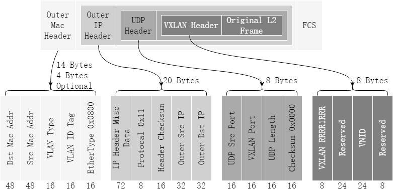
图17-1VXLAN报文格式
VXLAN头封装:
• Flag:8比特,目前协议取值为00001000,第五比特表示是否为有效VXLAN报文。
• VNID:VXLAN Network Identifier,VXLAN网络标识,24比特,用于区分VXLAN段。
• Reserved:24比特和8比特,目前协议规定需为全0。
UDP头封装:
• 目的端口号为4789,源端口号根据原始报文MAC、IP等信息通过哈希计算得到。
外层IP头:
• 源IP为发送报文的服务器或虚拟机所属VTEP的IP,目的IP为目的服务器或虚拟机所属VTEP的IP。
外层Ethernet头:
• Src MAC:发送报文VTEP的物理网络接口MAC。
• Dst MAC:目的VTEP IP在路由表中直连下一跳的MAC。
• VLAN:如底层物理网络使用了VLAN接口,则可选的带上相应的VLAN TAG。
转发原理 - 二层广播
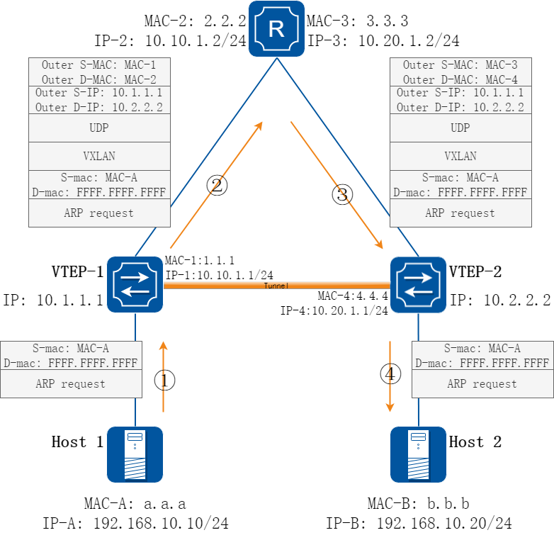
图17-2广播报文转发过程
如上图所示,HOST A与HOST B在同一网段,分布在不同的VTEP下面,HOST A与HOST B的通信过程详细如下:
• HOST A与HOST B处于同一网段,HOST A发送ARP请求HOST B的MAC地址。
• ARP请求报文到达VTEP-1后,交换机发现是广播报文需要在VLAN内广播,其中会有一份报文被送上VXLAN隧道(广播采用头端复制,如果有多条隧道,那么就会每条隧道发送一份报文),VLAN一一对应映射到VNI加上VXLAN封装,同时加上外层UDP、IP封装,根据外层IP查找路由表确定报文的下一跳。同时交换机在相应的VLAN内,学习地址Mac-A到eth-0-1接口。
• 报文在网络上根据外层IP进行转发,最终到达VTEP-2。
• VTEP-2 收到报文后发现外层Outer D-mac是本地地址,同时根据报文的Outer S-IP,Outer D-IP,VNI检查本地是否配置有相应的隧道,如有则进行解封装操作,去掉外层头后将VNI映射到相应VLAN,发现是广播报文时在VLAN内广播。同时在VLAN学习Mac-A到到相应的隧道接口。
转发原理 - 二层单播
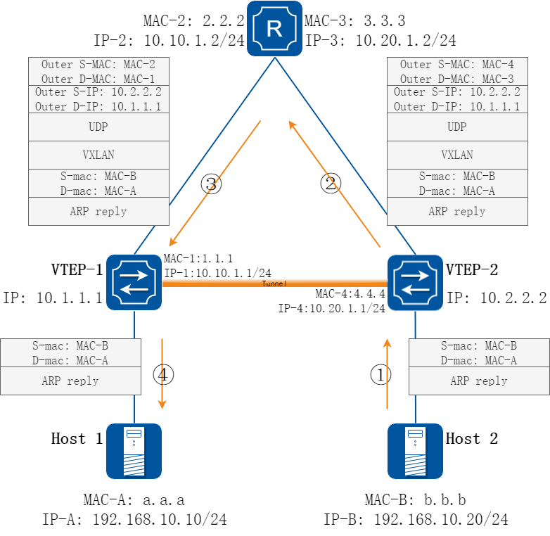
图17-3单播报文转发
如上图所示,HOST B回应HOST A发送的ARP请求,该报文为单播报文,以此为例说明单播报文转发流程:
• HOST B发送ARP应答,通过eth-0-1到达交换机VTEP-2
• 在VTEP-2上,根据Dst-mac查mac地址表,发现该VLAN内Mac-B的出接口为VXLAN隧道,远端VTEP为10.1.1.1,则将原始报文所在VLAN映射到VNI并加上VXLAN头部,同时加上外层MAC/IP头,Outer S-IP为本地VTEP IP,Outer D-IP为远端VTEP IP,Outer S-mac为本地出接口的mac,Outer D-mac为Outer D-IP对应的下一跳接口mac。
• 报文在网络上根据外层IP进行转发,最终到达VTEP-1。
• VTEP-1收到报文后发现外层Outer D-mac是本地地址,同时根据报文的Outer S-IP,Outer D-IP,VNI检查本地是否配置有相应的隧道,如有则进行解封装操作,去掉外层头后将VNI映射到相应VLAN,并根据原始报文的Dst-mac(Mac-A)查mac地址表,发现Mac-A的出接口为eth-0-1,则将解封装后的报文从eth-0-1口发送出去。同时在VLAN内学习Mac-B到相应的隧道接口。
![]() 默认VTEP两两间都建有隧道,如解封装后发现Dst-mac的出口为隧道,则报文会被丢弃。
默认VTEP两两间都建有隧道,如解封装后发现Dst-mac的出口为隧道,则报文会被丢弃。
转发原理 - 集中式VXLAN网关
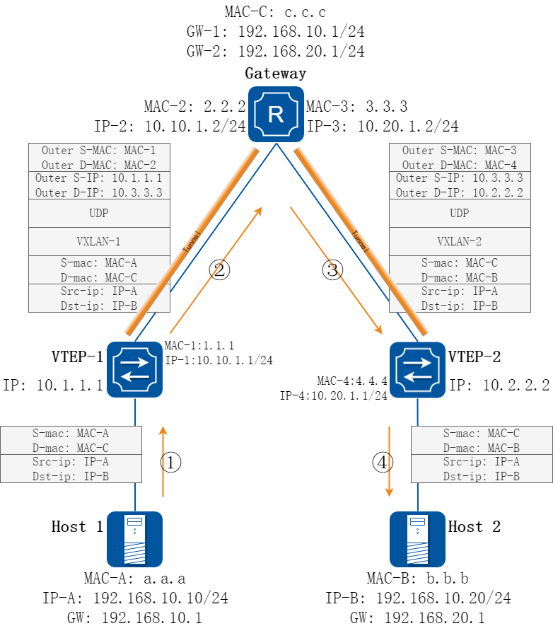
图17-4集中式网关示意
如上图所示, HOST A与B在不同网段,其间通信需要借助网关完成,此时可以将网关集中配置在VTEP-3上,VTEP-1和VTEP-2分别于VTEP-3建立VXLAN隧道,便于管理员进行集中管理
• HOST A发送arp-request来请求网关的mac地址,VTEP-1收到该请求后按未知单播流量将arp-request加vxlan封装后,转发给VTEP-3
• VTEP-3收到arp-request后判断自己是被请求的网关地址,于是给HOST A回应arp-reply并加上vxlan封装,同时学习HOST A的arp表项,其出口为vxlan隧道
• VTEP-1收到该arp-reply后,剥掉vxlan头,将原始的arp-reply转发给HOST A,同时学习gateway的mac地址,其出口为vxlan隧道
• HOST A收到该arp-reply后,学习到网关的mac地址,并开始发送数据报文,数据报文格式如图2-4所示
• Gateway收到收到该报文后,判断需要做路由转发,但是此时还没有HOST B的arp表项,因此发送arp-request来请求HOST B的arp,此arp-request会加到到VTEP-2的vxlan报文头
• VTEP-2收到该arp-request后,解封装转发给HOST B,同时学习gateway的mac地址,其出口为vxlan隧道 1.HOST B回应arp reply,其目的mac为gateway的mac,在VTEP-2上查找转发表,发现其出口为vxlan隧道,所以VTEP-2将该报文加vxlan封装发送给gateway
• Gateway收到该报文后,学习HOST B的arp,并将数据报文通过vxlan隧道转发给HOST B
转发原理 - 分布式VXLAN网关
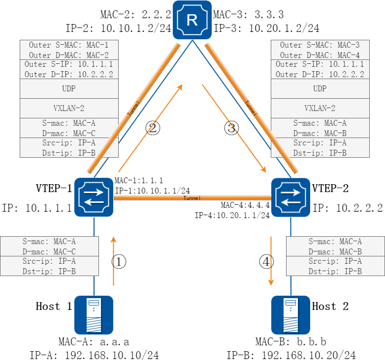
图17-5分布式网关示意
区别于集中式网关的路由功能集中在某一台设备上完成,分布式网关可以将路由功能分散到各接入的VTEP上,用以减轻集中式网关的压力。
如上图所示,根据组网可知IP-B为下联在VTEP-2下的主机,其所在VXLAN ID为VXLAN-2,根据上述信息,我们可以在报文入口VTEP(及图5中的VTEP-1)上配置路由表,将到IP-B的报文直接加上相应封装后发出,减轻网关压力的同时减小转发延时,具体转发流程如下:
• HOST A发出报文Dst-ip为IP-B,由于IP-B与本机ip(IP-A)不在同一网段,因此Dst-mac为网关mac(Mac-C)。
• 报文到达VTEP-1后,VTEP-1发现该报文的Dst-mac为VLAN网络内的网关mac,则去查找路由表是否有IP-B的路由信息。如有:则按路由表信息转发,该路由信息包含了IP-B所在的VTEP及VXLAN ID信息以及IP-B对应的mac(Mac-B)信息,在VTEP-1上将原始报文的Dst-mac修改为Mac-B后,加上相应的封装根据外层报文信息进行转发;如无:则丢弃该报文。
• 报文在网络上根据外层信息进行转发。
• 报文到达VTEP-2后进行解封装,解封装流程和二层转发相同。
![]() 分布式网关需要借助BGP EVPN来同步分布式网关上的arp表项,或者静态配置DVR路由。
分布式网关需要借助BGP EVPN来同步分布式网关上的arp表项,或者静态配置DVR路由。
2.周边特性
keep-vlan-tag
默认情况下,在加封装时会将原始报文中携带的VLAN标签剥掉,映射到外层的VXLAN-VNI,从而封装后报文的内层不再带有VLAN标签。在进入VXLAN网络的报文含有多层vlan tag情况下需要保留原始报文的VLAN标签,则需要配置隧道的keep-vlan-tag属性,具体配置方式请参见CLI手册。
tunnel-aware
报文经过VXLAN加封装后,传统网络设备只能识别报文外层头信息,并根据外层头信息进行转发。如网络发生拥塞等突发情况,由于无法识别报文内层信息将无法精确定位是由哪个虚机或服务器引起的拥塞。使能tunnel-aware功能后,将允许交换机分析报文内层原始报文信息,并将这些信息用于ACL,Flow tracing等,更利于精确的分析网络流量。
Distributed-Gateway
在分布式网关的应用场景中,服务器或虚拟机的网关配置在与自己相连的VTEP上,则在同一VTEP下的不同网段虚拟机之间通信不再需要通过集中式网关。如配合DVR路由使用可以不再部署集中式网关,具体配置方法可参看本文档配置举例章节相关案例。
split-horizon
默认情况下,从一条隧道来的流量不会再二层转发到另外一条隧道,如有隧道间流量相互转发的需求,需要配置将隧道上的split-horizon关闭。
隧道源地址
有些特殊场景,不同的隧道需要使用不同的源IP地址,可在创建隧道时指定不同的src-ip地址,交换机支持最多四个不同源地址。
DSCP策略
在隧道加封装时,可以配置加完封装后报文的DSCP生成策略,包括固定值/从原始报文中复制/根据报文的priority映射,默认从原始报文中复制。
17.1.2配置举例
配置vxlan
1.组网拓扑
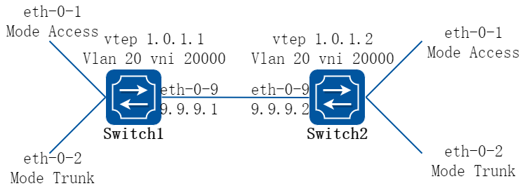
图17-6Vxlan
2.配置步骤
在下面的配置举例中,switch1和switch2间三层路由联通,通过VXLAN技术,将两台设备上vlan 20的流量封装在vni 20000中,从而实现跨越三层网络的互联互通。
以下配置如未说明在哪个Switch配置,则表示所有Switch配置相同:
步骤 1进入配置模式
Switch# configure terminal
步骤 2进入vlan配置模式并创建vlan,在vlan上使能overlay
Switch(config)# vlan database
Switch(config-vlan)# vlan 20
Switch(config-vlan)# vlan 20 overlay enable
Switch(config-vlan)# exit
步骤 3进入接口配置模式,配置接口属性
Switch1 的接口配置:
Switch1(config)# interface eth-0-1
Switch1(config-if)# switchport access vlan 20
Switch1(config-if)# no shutdown
Switch1(config-if)# exit
Switch1(config)# interface eth-0-2
Switch1(config-if)# switchport mode trunk
Switch1(config-if)# switchport trunk allowed vlan add 20
Switch1(config-if)# no shutdown
Switch1(config-if)# exit
Switch1(config)# interface eth-0-9
Switch1(config-if)# no switchport
Switch1(config-if)# ip address 9.9.9.1/24
Switch1(config-if)# overlay uplink enable
Switch1(config-if)# no shutdown
Switch1(config-if)# exit
Switch1(config)# interface loopback0
Switch1(config-if)# ip address 1.0.1.1/32
Switch1(config-if)# exit
Switch2 的接口配置:
Switch2(config)# interface eth-0-1
Switch2(config-if)# switchport access vlan 20
Switch2(config-if)# no shutdown
Switch2(config-if)# exit
Switch2(config)# interface eth-0-2
Switch2(config-if)# switchport mode trunk
Switch2(config-if)# switchport trunk allowed vlan add 20
Switch2(config-if)# no shutdown
Switch2(config-if)# exit
Switch2(config)# interface eth-0-9
Switch2(config-if)# no switchport
Switch2(config-if)# ip address 9.9.9.2/24
Switch2(config-if)# overlay uplink enable
Switch2(config-if)# no shutdown
Switch2(config-if)# exit
Switch2(config)# interface loopback0
Switch2(config-if)# ip address 1.0.1.2/32
Switch2(config-if)# exit
步骤 4配置静态路由
在switch1配置:
Switch1(config)# ip route 1.0.1.2/32 9.9.9.2
在switch2配置:
Switch2(config)# ip route 1.0.1.1/32 9.9.9.1
步骤 5配置overlay
在switch1配置:
Switch1(config)# overlay
Switch1(config-overlay)# source 1.0.1.1
Switch1(config-overlay)# remote-vtep 1 ip-address 1.0.1.2 type vxlan
Switch1(config-overlay)# vlan 20 vni 20000
Switch1(config-overlay)# vlan 20 remote-vtep 1
Switch1(config-overlay)# exit
在switch2配置:
Switch2(config)# overlay
Switch2(config-overlay)# source 1.0.1.2
Switch2(config-overlay)# remote-vtep 1 ip-address 1.0.1.1 type vxlan
Switch2(config-overlay)# vlan 20 vni 20000
Switch2(config-overlay)# vlan 20 remote-vtep 1
Switch2(config-overlay)# exit
步骤 6退出配置模式
Switch(config)# end
步骤 7检查配置
Switch1 显示结果:
Switch1# show overlay vlan 20
-------------------------------------------------------------------------------
ECMP Mode : Normal
Source VTEP : 1.0.1.1
-------------------------------------------------------------------------------
VLAN ID : 20
VNI : 20000
EVPN Tunnel Data-fdb Learning : Enable
Remote VTEP NUM : 1
Index: 1, Ip address: 1.0.1.2, Source ip: 1.0.1.1, Type: VxLAN, Protocol: Static
DVR Gateway NUM: 0
-------------------------------------------------------------------------
Switch2 显示结果:
Switch2# show overlay vlan 20
-------------------------------------------------------------------------------
ECMP Mode : Normal
Source VTEP : 1.0.1.2
-------------------------------------------------------------------------------
VLAN ID : 20
VNI : 20000
EVPN Tunnel Data-fdb Learning : Eanble
Remote VTEP NUM : 1
Index: 1, Ip address: 1.0.1.1, Source ip: 1.0.1.2, Type: VxLAN, Protocol: Static
DVR Gateway NUM: 0
-------------------------------------------------------------------------------
配置vxlan分布式路由
1.组网拓扑

图17-7Vxlan
2.配置步骤
在下面的配置举例中,按上图所示,VM-1和VM-3在同一个VNI中,通过VXLAN互联建立分布式路由;VM-2和VM-4在同一个VNI中,通过VXLAN互联建立分布式路由。
以下配置如未说明在哪个Switch配置,则表示所有Switch配置相同:
步骤 1进入配置模式
Switch# configure terminal
步骤 2进入vlan配置模式并创建vlan,在vlan上使能overlay
Switch(config)# vlan database
Switch(config-vlan)# vlan 20,30
Switch(config-vlan)# vlan 20 overlay enable
Switch(config-vlan)# vlan 30 overlay enable
Switch(config-vlan)# exit
步骤 3创建vrf实例
Switch(config)# ip vrf tenant
Switch(config-vrf)# exit
步骤 4创建三层接口,加入vrf并配置地址
在switch1配置:
Switch1(config)# interface vlan 20
Switch1(config-if)# ip vrf forwarding tenant
Switch1(config-if)# ip address 2.2.2.111/24
Switch1(config-if)# exit
Switch1(config)# interface vlan 30
Switch1(config-if)# ip vrf forwarding tenant
Switch1(config-if)# ip address 3.3.3.111/24
Switch1(config-if)# exit
在switch2配置:
Switch2(config)# interface vlan 20
Switch2(config-if)# ip vrf forwarding tenant
Switch2(config-if)# ip address 2.2.2.222/24
Switch2(config-if)# exit
Switch2(config)# interface vlan 30
Switch2(config-if)# ip vrf forwarding tenant
Switch2(config-if)# ip address 3.3.3.222/24
Switch2(config-if)# exit
步骤 5进入接口配置模式,配置接口属性
Switch(config)# interface eth-0-1
Switch(config-if)# switchport mode trunk
Switch(config-if)# switchport trunk allowed vlan add 20
Switch(config-if)# no shutdown
Switch(config-if)# exit
Switch(config)# interface eth-0-2
Switch(config-if)# switchport mode trunk
Switch(config-if)# switchport trunk allowed vlan add 30
Switch(config-if)# no shutdown
Switch(config-if)# exit
在switch1配置:
Switch1(config)# interface eth-0-9
Switch1(config-if)# no switchport
Switch1(config-if)# ip address 9.9.9.1/24
Switch1(config-if)# overlay uplink enable
Switch1(config-if)# no shutdown
Switch1(config-if)# exit
Switch1(config)# interface loopback0
Switch1(config-if)# ip address 1.0.1.1/32
Switch1(config-if)# exit
在switch2配置:
Switch2(config)# interface eth-0-9
Switch2(config-if)# no switchport
Switch2(config-if)# ip address 9.9.9.2/24
Switch2(config-if)# overlay uplink enable
Switch2(config-if)# no shutdown
Switch2(config-if)# exit
Switch2(config)# interface loopback0
Switch2(config-if)# ip address 1.0.1.2/32
Switch2(config-if)# exit
步骤 6配置overlay
在switch1配置:
Switch1(config)# overlay
Switch1(config-overlay)# source 1.0.1.1
Switch1(config-overlay)# remote-vtep 1 ip-address 1.0.1.2 type vxlan
Switch1(config-overlay)# remote-vtep 1 virtual-mac 22.22.22
Switch1(config-overlay)# vlan 20 vni 20000
Switch1(config-overlay)# vlan 30 vni 30000
Switch1(config-overlay)# vlan 20 remote-vtep 1
Switch1(config-overlay)# vlan 30 remote-vtep 1
Switch1(config-overlay)# vlan 20 gateway-mac a.a.a
Switch1(config-overlay)# vlan 30 gateway-mac b.b.b
Switch1(config-overlay)# exit
在switch2配置:
Switch2(config)# overlay
Switch2(config-overlay)# source 1.0.1.2
Switch2(config-overlay)# remote-vtep 1 ip-address 1.0.1.1 type vxlan
Switch2(config-overlay)# remote-vtep 1 virtual-mac 11.11.11
Switch2(config-overlay)# vlan 20 vni 20000
Switch2(config-overlay)# vlan 30 vni 30000
Switch2(config-overlay)# vlan 20 remote-vtep 1
Switch2(config-overlay)# vlan 30 remote-vtep 1
Switch2(config-overlay)# vlan 20 gateway-mac a.a.a
Switch2(config-overlay)# vlan 30 gateway-mac b.b.b
Switch2(config-overlay)# exit
步骤 7配置静态路由和vxlan分布式路由
在switch1配置:
Switch1(config)# ip route 1.0.1.2/32 9.9.9.2
Switch1(config)# ip route vrf tenant 2.2.2.2/32 remote-vtep 1 vni 20000 inner-macda 3.3.3
Switch1(config)# ip route vrf tenant 3.3.3.2/32 remote-vtep 1 vni 30000 inner-macda 4.4.4
在switch2配置:
Switch2(config)# ip route 1.0.1.1/32 9.9.9.1
Switch2(config)# ip route vrf tenant 2.2.2.1/32 remote-vtep 1 vni 20000 inner-macda 1.1.1
Switch2(config)# ip route vrf tenant 3.3.3.1/32 remote-vtep 1 vni 30000 inner-macda 2.2.2
步骤 8退出配置模式
Switch(config)# end
步骤 9检查配置
Switch1 显示结果:
Switch1# show ip route vrf tenant
Codes: K - kernel, C - connected, S - static, R - RIP, B - BGP
O - OSPF, IA - OSPF inter area
N1 - OSPF NSSA external type 1, N2 - OSPF NSSA external type 2
E1 - OSPF external type 1, E2 - OSPF external type 2
i - IS-IS, L1 - IS-IS level-1, L2 - IS-IS level-2, ia - IS-IS inter area
Dc - DHCP Client
[*] - [AD/Metric]
* - candidate default
S 2.2.2.2/32 is in overlay remote vxlan vtep:1.0.1.1->1.0.1.2, vni:20000
S 3.3.3.2/32 is in overlay remote vxlan vtep:1.0.1.1->1.0.1.2, vni:30000
Switch2 显示结果:
Switch2# show ip route vrf tenant
Codes: K - kernel, C - connected, S - static, R - RIP, B - BGP
O - OSPF, IA - OSPF inter area
N1 - OSPF NSSA external type 1, N2 - OSPF NSSA external type 2
E1 - OSPF external type 1, E2 - OSPF external type 2
i - IS-IS, L1 - IS-IS level-1, L2 - IS-IS level-2, ia - IS-IS inter area
Dc - DHCP Client
[*] - [AD/Metric]
* - candidate default
S 2.2.2.1/32 is in overlay remote vxlan vtep:1.0.1.2->1.0.1.1, vni:20000
S 3.3.3.1/32 is in overlay remote vxlan vtep:1.0.1.2->1.0.1.1, vni:30000
配置vxlan分布式路由的EBGP EVPN方式
1.组网拓扑
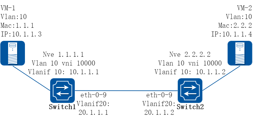
图17-8EBGP_EVPN
2.配置步骤
在下面的配置举例中,按上图所示,VM-1和VM-2在同一个VNI中,通过EBGP EVPN进行VXLAN隧道信息发布和主机信息发布,经过VXLAN互联建立分布式路由;
以下配置如未说明在哪个Switch配置,则表示所有Switch配置相同:
步骤 1进入配置模式
Switch# configure terminal
步骤 2进入vlan配置模式并创建vlan,在vlan上使能overlay
Switch(config)# vlan database
Switch(config-vlan)# vlan 10,20
Switch(config-vlan)# vlan 10 overlay enable
Switch(config-vlan)# exit
可选配置:使能vlan上的arp广播抑制功能
Switch(config)# vlan database
Switch(config-vlan)# vlan 10 arp-broadcast-suppress enable
Switch(config-vlan)# exit
步骤 3配置overlay的vlan vni
Switch(config)# overlay
Switch(config-overlay)# vlan 10 vni 10000
可选配置:去使能overlay上的inner fdb学习
Switch(config-overlay)# vlan 10 mac-address-tunnel learning-disable
退出overlay配置模式
Switch(config-overlay)# exit
步骤 4配置evpn实例
Switch(config)# evpn
Switch(config-evpn)# vni 10000
Switch(config-evi)# rd auto
Switch(config-evi)# route-target both 1:10000
Switch(config-evi)# exit
步骤 5创建vrf实例并使能EVPN
在switch1配置:
Switch1(config)# ip vrf tenant
Switch1(config-vrf)# rd 1:20000
Switch1(config-vrf)# route-target both 1:10000 evpn
Switch1(config-vrf)# vxlan vni 20000
Switch1(config-vrf)# exit
在switch2配置:
Switch2(config)# ip vrf tenant
Switch2(config-vrf)# rd 2:20000
Switch2(config-vrf)# route-target both 1:10000 evpn
Switch2(config-vrf)# vxlan vni 20000
Switch2(config-vrf)# exit
步骤 6创建三层接口,加入vrf并配置地址, 使能分布式网关
在switch1配置:
Switch1(config)# interface vlan 10
Switch1(config-if)# ip vrf forwarding tenant
Switch1(config-if)# overlay distributed-gateway enable
Switch1(config-if)# overlay host-collect enable
Switch1(config-if)# ip address 10.1.1.1/24
Switch1(config-if)# exit
Switch1(config)# interface vlan 20
Switch1(config-if)# ip address 20.1.1.1/24
Switch1(config-if)# exit
在switch2配置:
Switch2(config)# interface vlan 10
Switch2(config-if)# ip vrf forwarding tenant
Switch2(config-if)# overlay distributed-gateway enable
Switch2(config-if)# overlay host-collect enable
Switch2(config-if)# ip address 10.1.1.2/24
Switch2(config-if)# exit
Switch2(config)# interface vlan 20
Switch2(config-if)# ip address 20.1.1.2/24
Switch2(config-if)# exit
步骤 7进入接口配置模式,配置接口属性
Switch(config)# interface eth-0-1
Switch(config-if)# switchport access vlan 10
Switch(config-if)# no shutdown
Switch(config-if)# exit
Switch(config)# interface eth-0-9
Switch(config-if)# switchport mode trunk
Switch(config-if)# switchport trunk allowed vlan add 20
Switch(config-if)# vxlan uplink enable
Switch(config-if)# no shutdown
Switch(config-if)# exit
步骤 8配置overlay的NVE接口
在switch1配置:
Switch1(config)# interface loopback 1
Switch1(config-if)# ip address 1.1.1.1/32
Switch1(config-if)# exit
Switch1(config)# interface nve 1
Switch1(config-if)# source loopback 1
Switch1(config-if)# member vni 10000
Switch1(config-if)# member vni 20000 associate-vrf
Switch1(config-if)# exit
在switch2配置:
Switch2(config)# interface loopback 1
Switch2(config-if)# ip address 2.2.2.2/32
Switch2(config-if)# exit
Switch2(config)# interface nve 1
Switch2(config-if)# source loopback 1
Switch2(config-if)# member vni 10000
Switch2(config-if)# member vni 20000 associate-vrf
可选配置:配置EVPN VXLAN的tunnel属性
Switch2(config-if)# keep-vlan-tag enable
Switch2(config-if)# split-horizon disable
Switch2(config-if)# encapsulation-dscp-strategy custom-assign 63
Switch2(config-if)# virtual-mac a.a.a
Switch2(config-if)# exit
步骤 9配置BGP EVPN
在switch1配置:
Switch1(config)# router bgp 100
Switch1(config-router)# neighbor 20.1.1.2 remote-as 200
Switch1(config-router)# address-family l2vpn evpn
Switch1(config-router-af)# neighbor 20.1.1.2 activate
Switch1(config-router-af)# neighbor 20.1.1.2 send-community extended
Switch1(config-router-af)# neighbor 20.1.1.2 attribute-unchanged next-hop
Switch1(config-router-af)# exit
Switch1(config-router)# exit
在switch2配置:
Switch2(config)# router bgp 200
Switch2(config-router)# neighbor 20.1.1.1 remote-as 100
Switch2(config-router)# address-family l2vpn evpn
Switch2(config-router-af)# neighbor 20.1.1.1 activate
Switch2(config-router-af)# neighbor 20.1.1.1 send-community extended
Switch2(config-router-af)# neighbor 20.1.1.1 attribute-unchanged next-hop
Switch2(config-router-af)# exit
Switch2(config-router)# exit
步骤 10配置静态路由
在switch1配置:
Switch1(config)# ip route 2.2.2.2/32 20.1.1.2
在switch2配置:
Switch(config2)# ip route 1.1.1.1/32 20.1.1.1
步骤 11退出配置模式
Switch(config)# end
步骤 12检查配置
Switch1 显示结果:
Switch1# show bgp evpn all
Status codes: s suppressed, d damped, h history, * valid, > best, i - internal,
S Stale
Origin codes: i - IGP, e - EGP, ? - incomplete
Network Next Hop Metric LocPrf Weight Path
Route Distinguisher: 1:10000 (L2VNI 10000)
*> [2]:[0]:[48]:[4623.28ef.da00]:[32]:[0.0.0.0]/136
1.1.1.1 32768 i
*> [2]:[0]:[48]:[4623.28ef.da00]:[32]:[10.1.1.3]/136
1.1.1.1 32768 i
*> [2]:[0]:[48]:[ac7f.1cc5.fe00]:[32]:[0.0.0.0]/136
2.2.2.2 0 200 i
*> [2]:[0]:[48]:[ac7f.1cc5.fe00]:[32]:[10.1.1.4]/136
2.2.2.2 0 200 i
*> [3]:[0]:[32]:[1.1.1.1]/80
1.1.1.1 32768 i
*> [3]:[0]:[32]:[10.20.30.40]/80
2.2.2.2 0 200 i
Route Distinguisher: 1:10000
*> [2]:[0]:[48]:[ac7f.1cc5.fe00]:[32]:[0.0.0.0]/136
2.2.2.2 0 200 i
*> [2]:[0]:[48]:[ac7f.1cc5.fe00]:[32]:[10.1.1.4]/136
2.2.2.2 0 200 i
*> [3]:[0]:[32]:[2.2.2.2]/80
2.2.2.2 0 200 i
Route Distinguisher: 1:20000 (L3VNI 20000)
*> [2]:[0]:[48]:[ac7f.1cc5.fe00]:[32]:[10.1.1.4]/136
2.2.2.2
Switch1# show overlay tunnel
-------------------------------------------------------------------------------
Vlan Vni Type Remote-vtep IP-Address Src-Address Head-end-flooding Protocol
10 10000 VxLAN 0 2.2.2.2 1.1.1.1 Enable Evpn
Switch2 显示结果:
Head-end-floodingSwitch2# show bgp evpn all
Status codes: s suppressed, d damped, h history, * valid, > best, i - internal,
S Stale
Origin codes: i - IGP, e - EGP, ? - incomplete
Network Next Hop Metric LocPrf Weight Path
Route Distinguisher: 1:10000 (L2VNI 10000)
*> [2]:[0]:[48]:[4623.28ef.da00]:[32]:[0.0.0.0]/136
1.1.1.1 0 100 i
*> [2]:[0]:[48]:[4623.28ef.da00]:[32]:[10.1.1.3]/136
1.1.1.1 0 100 i
*> [2]:[0]:[48]:[ac7f.1cc5.fe00]:[32]:[0.0.0.0]/136
2.2.2.2 32768 i
*> [2]:[0]:[48]:[ac7f.1cc5.fe00]:[32]:[10.1.1.4]/136
2.2.2.2 32768 i
*> [3]:[0]:[32]:[1.1.1.1]/80
1.1.1.1 0 100 i
*> [3]:[0]:[32]:[2.2.2.2]/80
2.2.2.2 32768 i
Route Distinguisher: 1:10000
*> [2]:[0]:[48]:[4623.28ef.da00]:[32]:[0.0.0.0]/136
1.1.1.1 0 100 i
*> [2]:[0]:[48]:[4623.28ef.da00]:[32]:[10.1.1.3]/136
1.1.1.1 0 100 i
*> [3]:[0]:[32]:[1.1.1.1]/80
1.1.1.1 0 100 i
Route Distinguisher: 2:20000 (L3VNI 20000)
*> [2]:[0]:[48]:[4623.28ef.da00]:[32]:[10.1.1.3]/136
1.1.1.1 0 100 i
Switch2# show overlay tunnel
-------------------------------------------------------------------------------
Vlan Vni Type Remote-vtep IP-Address Src-Address Head-end-flooding Protocol
10 10000 VxLAN 0 1.1.1.1 2.2.2.2 Enable Evpn
配置vxlan分布式路由的IBGP EVPN方式
1.组网拓扑
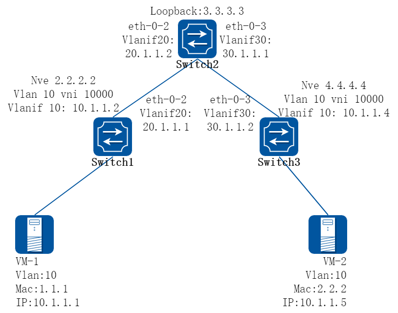
图17-9IBGP_EVPN
2.配置步骤
在下面的配置举例中,按上图所示,VM-1和VM-2在同一个VNI中,通过IBGP EVPN进行VXLAN隧道信息发布和主机信息发布,经过VXLAN互联建立分布式路由;中间通过路由反射器进行EVPN路由交换。
以下配置如未说明在哪个Switch配置,则表示所有Switch配置相同:
步骤 1进入配置模式
Switch# configure terminal
步骤 2进入vlan配置模式并创建vlan,在vlan上使能overlay
在switch1配置:
Switch1(config)# vlan database
Switch1(config-vlan)# vlan 10,20
Switch1(config-vlan)# vlan 10 overlay enable
Switch1(config-vlan)# exit
在switch2配置:
Switch2(config)# vlan database
Switch2(config-vlan)# vlan 20,30
Switch2(config-vlan)# exit
在switch3配置:
Switch3(config)# vlan database
Switch3(config-vlan)# vlan 10,30
Switch3(config-vlan)# vlan 10 overlay enable
Switch3(config-vlan)# exit
可选配置:使能vlan上的arp广播抑制功能
Switch3(config)# vlan database
Switch3(config-vlan)# vlan 10 arp-broadcast-suppress enable
Switch3(config-vlan)# exit
步骤 3配置overlay的vlan vni
在switch1配置:
Switch1(config)# overlay
Switch1(config-overlay)# vlan 10 vni 10000
可选配置:去使能overlay上的inner fdb学习
Switch1(config-overlay)# vlan 10 mac-address-tunnel learning-disable
退出overlay配置模式
Switch1(config-overlay)# exit
在switch3配置:
Switch3(config)# overlay
Switch3(config-overlay)# vlan 10 vni 10000
可选配置:去使能overlay上的inner fdb学习
Switch3(config-overlay)# vlan 10 mac-address-tunnel learning-disable
退出overlay配置模式
Switch3(config-overlay)# exit
步骤 4配置evpn实例
在switch1配置:
Switch1(config)# evpn
Switch1(config-evpn)# vni 10000
Switch1(config-evi)# rd 2:2
Switch1(config-evi)# route-target both 20:20
Switch1(config-evi)# exit
在switch2配置:
Switch2(config)# evpn
在switch3配置:
Switch3(config)# evpn
Switch3(config-evpn)# vni 10000
Switch3(config-evi)# rd 4:4
Switch3(config-evi)# route-target both 20:20
Switch3(config-evi)# exit
步骤 5创建vrf实例并使能EVPN
在switch1配置:
Switch1(config)# ip vrf tenant
Switch1(config-vrf)# rd 22:22
Switch1(config-vrf)# route-target both 20:20 evpn
Switch1(config-vrf)# vxlan vni 20000
Switch1(config-vrf)# exit
在switch3配置:
Switch3(config)# ip vrf tenant
Switch3(config-vrf)# rd 44:44
Switch3(config-vrf)# route-target both 20:20 evpn
Switch3(config-vrf)# vxlan vni 20000
Switch3(config-vrf)# exit
步骤 6创建三层接口,加入vrf并配置地址, 使能分布式网关
在switch1配置:
Switch1(config)# interface vlan 10
Switch1(config-if)# ip vrf forwarding tenant
Switch1(config-if)# overlay distributed-gateway enable
Switch1(config-if)# overlay host-collect enable
Switch1(config-if)# ip address 10.1.1.2/24
Switch1(config-if)# exit
Switch1(config)# interface vlan 20
Switch1(config-if)# ip address 20.1.1.1/24
Switch1(config-if)# exit
在switch2配置:
Switch2(config)# interface vlan 20
Switch2(config-if)# ip address 20.1.1.2/24
Switch2(config-if)# exit
Switch2(config)# interface vlan 30
Switch2(config-if)# ip address 30.1.1.1/24
Switch2(config-if)# exit
在switch3配置:
Switch3(config)# interface vlan 10
Switch3(config-if)# ip vrf forwarding tenant
Switch3(config-if)# overlay distributed-gateway enable
Switch3(config-if)# overlay host-collect enable
Switch3(config-if)# ip address 10.1.1.3/24
Switch3(config-if)# exit
Switch3(config)# interface vlan 30
Switch3(config-if)# ip address 30.1.1.2/24
Switch3(config-if)# exit
步骤 7进入接口配置模式,配置接口属性
在switch1配置:
Switch1(config)# interface eth-0-10
Switch1(config-if)# switchport access vlan 10
Switch1(config-if)# no shutdown
Switch1(config-if)# exit
Switch1(config)# interface eth-0-2
Switch1(config-if)# switchport mode trunk
Switch1(config-if)# switchport trunk allowed vlan add 20
Switch1(config-if)# vxlan uplink enable
Switch1(config-if)# no shutdown
Switch1(config-if)# exit
在switch2配置:
Switch2(config)# interface eth-0-2
Switch2(config-if)# switchport mode trunk
Switch2(config-if)# switchport trunk allowed vlan add 20
Switch2(config-if)# vxlan uplink enable
Switch2(config-if)# no shutdown
Switch2(config-if)# exit
Switch2(config)# interface eth-0-3
Switch2(config-if)# switchport mode trunk
Switch2(config-if)# switchport trunk allowed vlan add 30
Switch2(config-if)# vxlan uplink enable
Switch2(config-if)# no shutdown
Switch2(config-if)# exit
在switch3配置:
Switch3(config)# interface eth-0-10
Switch3(config-if)# switchport access vlan 10
Switch3(config-if)# no shutdown
Switch3(config-if)# exit
Switch3(config)# interface eth-0-3
Switch3(config-if)# switchport mode trunk
Switch3(config-if)# switchport trunk allowed vlan add 30
Switch3(config-if)# vxlan uplink enable
Switch3(config-if)# no shutdown
Switch3(config-if)# exit
步骤 8配置overlay的NVE接口
在switch1配置:
Switch1(config)# interface loopback 2
Switch1(config-if)# ip address 2.2.2.2/32
Switch1(config-if)# exit
Switch1(config)# interface nve 1
Switch1(config-if)# source 2.2.2.2
Switch1(config-if)# member vni 10000
Switch1(config-if)# member vni 20000 associate-vrf
Switch1(config-if)# exit
在switch2配置:
Switch2(config)# interface loopback 3
Switch2(config-if)# ip address 3.3.3.3/32
Switch2(config-if)# exit
在switch3配置:
Switch3(config)# interface loopback 4
Switch3(config-if)# ip address 4.4.4.4/32
Switch3(config-if)# exit
Switch3(config)# interface nve 1
Switch3(config-if)# source 4.4.4.4
Switch3(config-if)# member vni 10000
Switch3(config-if)# member vni 20000 associate-vrf
可选配置:配置EVPN VXLAN的tunnel属性
Switch3(config-if)# keep-vlan-tag enable
Switch3(config-if)# split-horizon disable
Switch3(config-if)# encapsulation-dscp-strategy custom-assign 63
Switch3(config-if)# virtual-mac a.a.a
Switch3(config-if)# exit
步骤 9配置BGP EVPN
在switch1配置:
Switch1(config)# router bgp 100
Switch1(config-router)# neighbor 3.3.3.3 remote-as 100
Switch1(config-router)# neighbor 3.3.3.3 update-source loopback2
Switch1(config-router)# neighbor 20.1.1.2 remote-as 100
Switch1(config-router)# address-family ipv4
Switch1(config-router-af)# network 2.2.2.2 mask 255.255.255.255
Switch1(config-router-af)# neighbor 20.1.1.2 weight 32768
Switch1(config-router-af)# exit
Switch1(config-router)# address-family l2vpn evpn
Switch1(config-router-af)# neighbor 3.3.3.3 activate
Switch1(config-router-af)# neighbor 3.3.3.3 send-community extended
Switch1(config-router-af)# exit
Switch1(config-router)# exit
在switch2配置:
Switch2(config)# router bgp 100
Switch2(config-router)# neighbor 2.2.2.2 remote-as 100
Switch2(config-router)# neighbor 2.2.2.2 update-source loopback3
Switch2(config-router)# neighbor 4.4.4.4 remote-as 100
Switch2(config-router)# neighbor 4.4.4.4 update-source loopback3
Switch2(config-router)# neighbor 20.1.1.1 remote-as 100
Switch2(config-router)# neighbor 30.1.1.2 remote-as 100
Switch2(config-router)# address-family ipv4
Switch2(config-router-af)# network 3.3.3.3 mask 255.255.255.255
Switch2(config-router-af)# network 20.1.1.0 mask 255.255.255.0
Switch2(config-router-af)# network 30.1.1.0 mask 255.255.255.0
Switch2(config-router-af)# neighbor 20.1.1.1 weight 32768
Switch2(config-router-af)# neighbor 20.1.1.1 route-reflector-client
Switch2(config-router-af)# neighbor 20.1.1.1 next-hop-self
Switch2(config-router-af)# neighbor 30.1.1.2 weight 32768
Switch2(config-router-af)# neighbor 30.1.1.2 route-reflector-client
Switch2(config-router-af)# neighbor 30.1.1.2 next-hop-self
Switch2(config-router-af)# exit
Switch2(config-router)# address-family l2vpn evpn
Switch2(config-router-af)# neighbor 2.2.2.2 activate
Switch2(config-router-af)# neighbor 2.2.2.2 route-reflector-client
Switch2(config-router-af)# neighbor 2.2.2.2 send-community extended
Switch2(config-router-af)# neighbor 4.4.4.4 activate
Switch2(config-router-af)# neighbor 4.4.4.4 route-reflector-client
Switch2(config-router-af)# neighbor 4.4.4.4 send-community extended
Switch2(config-router-af)# exit
Switch2(config-router)# exit
在switch3配置:
Switch3(config)# router bgp 100
Switch3(config-router)# neighbor 3.3.3.3 remote-as 100
Switch3(config-router)# neighbor 3.3.3.3 update-source loopback4
Switch3(config-router)# neighbor 30.1.1.1 remote-as 100
Switch3(config-router)# address-family ipv4
Switch3(config-router-af)# network 4.4.4.4 mask 255.255.255.255
Switch3(config-router-af)# neighbor 30.1.1.1 weight 32768
Switch3(config-router-af)# exit
Switch3(config-router)# address-family l2vpn evpn
Switch3(config-router-af)# neighbor 3.3.3.3 activate
Switch3(config-router-af)# neighbor 3.3.3.3 send-community extended
Switch3(config-router-af)# exit
Switch3(config-router)# exit
步骤 10退出配置模式
Switch(config)# end
步骤 11检查配置
Switch1 显示结果:
Switch1# show bgp evpn all
Status codes: s suppressed, d damped, h history, * valid, > best, i - internal,
S Stale
Origin codes: i - IGP, e - EGP, ? - incomplete
Network Next Hop Metric LocPrf Weight Path
Route Distinguisher: 2:2 (L2VNI 10000)
*> [2]:[0]:[48]:[988b.123a.4000]:[32]:[0.0.0.0]/136
2.2.2.2 32768 i
*> [2]:[0]:[48]:[988b.123a.4000]:[32]:[10.1.1.1]/136
2.2.2.2 32768 i
*> [3]:[0]:[32]:[2.2.2.2]/80
2.2.2.2 32768 i
*>i[3]:[0]:[32]:[4.4.4.4]/80
4.4.4.4 100 0 i
Route Distinguisher: 4:4
*>i[3]:[0]:[32]:[4.4.4.4]/80
4.4.4.4 100 0 i
Switch1# show overlay tunnel
-------------------------------------------------------------------------------
Vlan Vni Type Remote-vtep IP-Address Src-Address Head-end-flooding Protocol
10 10000 VxLAN 0 4.4.4.4 2.2.2.2 Enable Evpn
Switch2 显示结果:
Switch2# show bgp evpn all
Status codes: s suppressed, d damped, h history, * valid, > best, i - internal,
S Stale
Origin codes: i - IGP, e - EGP, ? - incomplete
Network Next Hop Metric LocPrf Weight Path
Route Distinguisher: 2:2
*>i[2]:[0]:[48]:[988b.123a.4000]:[32]:[0.0.0.0]/136
2.2.2.2 100 0 i
*>i[2]:[0]:[48]:[988b.123a.4000]:[32]:[10.1.1.1]/136
2.2.2.2 100 0 i
*>i[3]:[0]:[32]:[2.2.2.2]/80
2.2.2.2 100 0 i
Route Distinguisher: 4:4
*>i[3]:[0]:[32]:[4.4.4.4]/80
4.4.4.4 100 0 i
Switch3 显示结果:
Switch3# show bgp evpn all
Status codes: s suppressed, d damped, h history, * valid, > best, i - internal,
S Stale
Origin codes: i - IGP, e - EGP, ? - incomplete
Network Next Hop Metric LocPrf Weight Path
Route Distinguisher: 2:2
*>i[2]:[0]:[48]:[988b.123a.4000]:[32]:[0.0.0.0]/136
2.2.2.2 100 0 i
*>i[2]:[0]:[48]:[988b.123a.4000]:[32]:[10.1.1.1]/136
2.2.2.2 100 0 i
*>i[3]:[0]:[32]:[2.2.2.2]/80
2.2.2.2 100 0 i
Route Distinguisher: 4:4 (L2VNI 10000)
*>i[2]:[0]:[48]:[988b.123a.4000]:[32]:[0.0.0.0]/136
2.2.2.2 100 0 i
*>i[2]:[0]:[48]:[988b.123a.4000]:[32]:[10.1.1.1]/136
2.2.2.2 100 0 i
*>i[3]:[0]:[32]:[2.2.2.2]/80
2.2.2.2 100 0 i
*> [3]:[0]:[32]:[4.4.4.4]/80
4.4.4.4 32768 i
Route Distinguisher: 44:44 (L3VNI 20000)
*>i[2]:[0]:[48]:[988b.123a.4000]:[32]:[10.1.1.1]/136
2.2.2.2 100 0 i
Switch3# show overlay tunnel
-------------------------------------------------------------------------------
Vlan Vni Type Remote-vtep IP-Address Src-Address Head-end-flooding Protocol
10 10000 VxLAN 0 2.2.2.2 4.4.4.4 Enable Evpn
Switch3# show mac address-table
Mac Address Table
-------------------------------------------
(*) - Security Entry (M) - MLAG Entry
(MO) - MLAG Output Entry (MI) - MLAG Input Entry
Vlan Mac Address Type Ports
---- ----------- -------- -----
30 fcc0.9318.0a00 dynamic eth-0-9
10 988b.123a.4000 dynamic VxLAN: 4.4.4.4->2.2.2.2(EI)
Switch3# show ip route vrf tenant
Codes: K - kernel, C - connected, S - static, R - RIP, B - BGP
O - OSPF, IA - OSPF inter area
N1 - OSPF NSSA external type 1, N2 - OSPF NSSA external type 2
E1 - OSPF external type 1, E2 - OSPF external type 2
i - IS-IS, L1 - IS-IS level-1, L2 - IS-IS level-2, ia - IS-IS inter area
Dc - DHCP Client
[*] - [AD/Metric]
* - candidate default
C 10.1.1.0/24 is directly connected, vlan10
C 10.1.1.3/32 is in local loopback, vlan10
B 10.1.1.1/32 is in overlay remote vxlan vtep:4.4.4.4->2.2.2.2, vni:20000
基于IPv6网络配置vxlan
1.组网拓扑
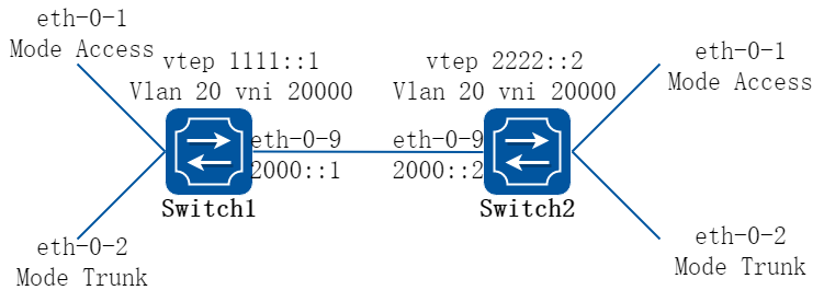
图17-10Vxlan
2.配置步骤
在下面的配置举例中,switch1和switch2间三层路由联通,通过VXLAN技术,将两台设备上vlan 20的流量封装在vni 20000中,从而实现跨越三层网络的互联互通。
以下配置如未说明在哪个Switch配置,则表示所有Switch配置相同:
步骤 1进入配置模式
Switch# configure terminal
步骤 2进入vlan配置模式并创建vlan,在vlan上使能overlay
Switch(config)# vlan database
Switch(config-vlan)# vlan 20
Switch(config-vlan)# vlan 20 overlay enable
Switch(config-vlan)# exit
步骤 3进入接口配置模式,配置接口属性
Switch1 的接口配置:
Switch1(config)# ipv6 enable
Switch1(config)# interface eth-0-1
Switch1(config-if)# switchport access vlan 20
Switch1(config-if)# no shutdown
Switch1(config-if)# exit
Switch1(config)# interface eth-0-2
Switch1(config-if)# switchport mode trunk
Switch1(config-if)# switchport trunk allowed vlan add 20
Switch1(config-if)# no shutdown
Switch1(config-if)# exit
Switch1(config)# interface eth-0-9
Switch1(config-if)# no switchport
Switch1(config-if)# ipv6 address 2000::1/64
Switch1(config-if)# vxlan uplink enable
Switch1(config-if)# no shutdown
Switch1(config-if)# exit
Switch1(config)# interface loopback0
Switch1(config-if)# ipv6 address 1111::1/128
Switch1(config-if)# exit
Switch2 的接口配置:
Switch2(config)# interface eth-0-1
Switch2(config-if)# switchport access vlan 20
Switch2(config-if)# no shutdown
Switch2(config-if)# exit
Switch2(config)# interface eth-0-2
Switch2(config-if)# switchport mode trunk
Switch2(config-if)# switchport trunk allowed vlan add 20
Switch2(config-if)# no shutdown
Switch2(config-if)# exit
Switch2(config)# interface eth-0-9
Switch2(config-if)# no switchport
Switch2(config-if)# ipv6 address 2000::2/64
Switch2(config-if)# vxlan uplink enable
Switch2(config-if)# no shutdown
Switch2(config-if)# exit
Switch2(config)# interface loopback0
Switch2(config-if)# ipv6 address 2222::2/128
Switch2(config-if)# exit
步骤 4配置静态路由
在switch1配置:
Switch1(config)# ipv6 route 2222::2/128 2000::2
在switch2配置:
Switch2(config)# ipv6 route 1111::1/128 2000::1
步骤 5配置overlay
在switch1配置:
Switch1(config)# overlay
Switch1(config-overlay)# source 1111::1
Switch1(config-overlay)# remote-vtep 1 ipv6-address 2222::2 type vxlan
Switch1(config-overlay)# vlan 20 vni 20000
Switch1(config-overlay)# vlan 20 remote-vtep 1
Switch1(config-overlay)# exit
在switch2配置:
Switch2(config)# overlay
Switch2(config-overlay)# source 2222::2
Switch2(config-overlay)# remote-vtep 1 ipv6-address 2222::2 type vxlan
Switch2(config-overlay)# vlan 20 vni 20000
Switch2(config-overlay)# vlan 20 remote-vtep 1
Switch2(config-overlay)# exit
步骤 6退出配置模式
Switch(config)# end
步骤 7检查配置
Switch1 显示结果:
Switch1# show overlay vlan 20
-------------------------------------------------------------------------------
ECMP Mode : Normal
Source VTEP : 1111::1
-------------------------------------------------------------------------------
VLAN ID : 20
VNI : 20000
EVPN Tunnel Data-fdb Learning : Enable
Remote VTEP NUM : 1
Index: 1, Type: VxLAN, Protocol: Static
IP address: 2222::2
Source ip : 1111::1
DVR Gateway NUM: 0
-------------------------------------------------------------------------
Switch2 显示结果:
Switch2# show overlay vlan 20
-------------------------------------------------------------------------------
ECMP Mode : Normal
Source VTEP : 2222::2
-------------------------------------------------------------------------------
VLAN ID : 20
VNI : 20000
EVPN Tunnel Data-fdb Learning : Enable
Remote VTEP NUM : 1
Index: 1, Type: VxLAN, Protocol: Static
IP address: 1111::1
Source ip : 2222::2
DVR Gateway NUM: 0
-------------------------------------------------------------------------
基于IPv6配置vxlan分布式路由
1.组网拓扑

图17-11Vxlan
2.配置步骤
在下面的配置举例中,按上图所示,VM-1和VM-3在同一个VNI中,通过VXLAN互联建立分布式路由;VM-2和VM-4在同一个VNI中,通过VXLAN互联建立分布式路由。
以下配置如未说明在哪个Switch配置,则表示所有Switch配置相同:
步骤 1进入配置模式
Switch# configure terminal
步骤 2进入vlan配置模式并创建vlan,在vlan上使能overlay
Switch(config)# vlan database
Switch(config-vlan)# vlan 20,30
Switch(config-vlan)# vlan 20 overlay enable
Switch(config-vlan)# vlan 30 overlay enable
Switch(config-vlan)# exit
步骤 3创建vrf实例
Switch(config)# ip vrf tenant
Switch(config-vrf)# exit
步骤 4创建三层接口,加入vrf并配置地址
在switch1配置:
Switch1(config)# ipv6 enable
Switch1(config)# interface vlan 20
Switch1(config-if)# ip vrf forwarding tenant
Switch1(config-if)# ipv6 address 2000::111/64
Switch1(config-if)# exit
Switch1(config)# interface vlan 30
Switch1(config-if)# ip vrf forwarding tenant
Switch1(config-if)# ipv6 address 3000::111/64
Switch1(config-if)# exit
在switch2配置:
Switch2(config)# interface vlan 20
Switch2(config-if)# ip vrf forwarding tenant
Switch2(config-if)# ipv6 address 2000::222/24
Switch2(config-if)# exit
Switch2(config)# interface vlan 30
Switch2(config-if)# ip vrf forwarding tenant
Switch2(config-if)# ipv6 address 3000::222/24
Switch2(config-if)# exit
步骤 5进入接口配置模式,配置接口属性
Switch(config)# interface eth-0-1
Switch(config-if)# switchport mode trunk
Switch(config-if)# switchport trunk allowed vlan add 20
Switch(config-if)# no shutdown
Switch(config-if)# exit
Switch(config)# interface eth-0-2
Switch(config-if)# switchport mode trunk
Switch(config-if)# switchport trunk allowed vlan add 30
Switch(config-if)# no shutdown
Switch(config-if)# exit
在switch1配置:
Switch1(config)# interface eth-0-9
Switch1(config-if)# no switchport
Switch1(config-if)# ipv6 address 1234::1/64
Switch1(config-if)# vxlan uplink enable
Switch1(config-if)# no shutdown
Switch1(config-if)# exit
Switch1(config)# interface loopback0
Switch1(config-if)# ipv6 address 1111::1/128
Switch1(config-if)# exit
在switch2配置:
Switch2(config)# interface eth-0-9
Switch2(config-if)# no switchport
Switch2(config-if)# ipv6 address 1234::2/64
Switch2(config-if)# vxlan uplink enable
Switch2(config-if)# no shutdown
Switch2(config-if)# exit
Switch2(config)# interface loopback0
Switch2(config-if)# ipv6 address 2222::2/128
Switch2(config-if)# exit
步骤 6配置overlay
在switch1配置:
Switch1(config)# overlay
Switch1(config-overlay)# source 1111::1
Switch1(config-overlay)# remote-vtep 1 ipv6-address 2222::2 type vxlan
Switch1(config-overlay)# vlan 20 vni 20000
Switch1(config-overlay)# vlan 30 vni 30000
Switch1(config-overlay)# vlan 20 remote-vtep 1
Switch1(config-overlay)# vlan 30 remote-vtep 1
Switch1(config-overlay)# vlan 20 gateway-mac a.a.a
Switch1(config-overlay)# vlan 30 gateway-mac b.b.b
Switch1(config-overlay)# exit
在switch2配置:
Switch2(config)# overlay
Switch2(config-overlay)# source 2222::2
Switch2(config-overlay)# remote-vtep 1 ipv6-address 1111::1 type vxlan
Switch2(config-overlay)# vlan 20 vni 20000
Switch2(config-overlay)# vlan 30 vni 30000
Switch2(config-overlay)# vlan 20 remote-vtep 1
Switch2(config-overlay)# vlan 30 remote-vtep 1
Switch2(config-overlay)# vlan 20 gateway-mac a.a.a
Switch2(config-overlay)# vlan 30 gateway-mac b.b.b
Switch2(config-overlay)# exit
步骤 7配置静态路由和vxlan分布式路由
在switch1配置:
Switch1(config)# ipv6 route 2222::2/128 1234::2
Switch1(config)# ipv6 route vrf tenant 2000::2/128 remote-vtep 1 vni 20000 inner-macda 3.3.3
Switch1(config)# ipv6 route vrf tenant 3000::2/128 remote-vtep 1 vni 30000 inner-macda 4.4.4
在switch2配置:
Switch2(config)# ipv6 route 1111::1/128 1234::1
Switch2(config)# ipv6 route vrf tenant 2000::1/32 remote-vtep 1 vni 20000 inner-macda 1.1.1
Switch2(config)# ipv6 route vrf tenant 3000::1/32 remote-vtep 1 vni 30000 inner-macda 2.2.2
步骤 8退出配置模式
Switch(config)# end
步骤 9检查配置
Switch1 显示结果:
Switch1# show ipv6 route vrf tenant
Codes: C - connected, S - static, R - RIP, I - IS-IS, B - BGP
O - OSPF, IA - OSPF inter area
N1 - OSPF NSSA external type 1, N2 - OSPF NSSA external type 2
E1 - OSPF external type 1, E2 - OSPF external type 2
Dr - DHCPV6 Relay
[*] - [AD/Metric]
S 2000::2/128 is in overlay remote vxlan vtep:1111::1->2222::2, vni:20000
S 3000::2/128 is in overlay remote vxlan vtep:1111::1->2222::2, vni:30000
Switch2 显示结果:
Switch2# show ipv6 route vrf tenant
Codes: C - connected, S - static, R - RIP, I - IS-IS, B - BGP
O - OSPF, IA - OSPF inter area
N1 - OSPF NSSA external type 1, N2 - OSPF NSSA external type 2
E1 - OSPF external type 1, E2 - OSPF external type 2
Dr - DHCPV6 Relay
[*] - [AD/Metric]
S 2000::1/128 is in overlay remote vxlan vtep:2222::2->1111::1, vni:20000
S 3000::1/128 is in overlay remote vxlan vtep:2222::2->1111::1, vni:30000
用户同网段通过VXLAN网络互通
1.组网拓扑
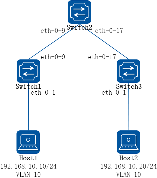
图17-12VXLAN网络互通组网图
2.组网需求
Host 1和Host 2处于同一网段, 需要通过VXLAN隧道来实现互通。
3.配置步骤
步骤 1分别在SWITCH 1、SWITCH 2、SWITCH 3上配置路由,保证交换机之间三层网络可通
配置SWITCH 1
SWITCH_1# configure terminal
Enter configuration commands, one per line. End with CNTL/Z.
SWITCH_1(config)# interface loopback 0
SWITCH_1(config-if)# ip address 10.1.1.1/32
SWITCH_1(config-if)# exit
SWITCH_1(config)# interface eth-0-9
SWITCH_1(config-if)# no switchport
SWITCH_1(config-if)# ip address 192.168.1.1/24
SWITCH_1(config-if)# vxlan uplink enable
SWITCH_1(config-if)# no shutdown
SWITCH_1(config-if)# exit
SWITCH_1(config)# ip route 10.3.3.3/32 192.168.1.2
SWITCH_1(config)# end
配置SWITCH 2
SWITCH_2# configure terminal
Enter configuration commands, one per line. End with CNTL/Z.
SWITCH_2(config)# interface eth-0-9
SWITCH_2(config-if)# no switchport
SWITCH_2(config-if)# ip address 192.168.1.2/24
SWITCH_2(config-if)# no shutdown
SWITCH_2(config-if)# exit
SWITCH_2(config)# interface eth-0-17
SWITCH_2(config-if)# no switchport
SWITCH_2(config-if)# ip address 192.168.2.1/24
SWITCH_2(config-if)# no shutdown
SWITCH_2(config-if)# exit
SWITCH_2(config)# ip route 10.1.1.1/32 192.168.1.1
SWITCH_2(config)# ip route 10.3.3.3/32 192.168.2.2
SWITCH_2(config)# end
配置SWITCH 3
SWITCH_3# configure terminal
Enter configuration commands, one per line. End with CNTL/Z.
SWITCH_3(config)# interface loopback 0
SWITCH_3(config-if)# ip address 10.3.3.3/32
SWITCH_3(config-if)# exit
SWITCH_3(config)# interface eth-0-17
SWITCH_3(config-if)# no switchport
SWITCH_3(config-if)# ip address 192.168.2.2/24
SWITCH_3(config-if)# vxlan uplink enable
SWITCH_3(config-if)# no shutdown
SWITCH_3(config-if)# exit
SWITCH_3(config)# ip route 10.1.1.1/32 192.168.2.1
SWITCH_3(config)# end
步骤 2分别在SWITCH 1、SWITCH 3上配置VLAN
配置SWITCH 1
SWITCH_1# configure terminal
Enter configuration commands, one per line. End with CNTL/Z.
SWITCH_1(config)# vlan database
SWITCH_1(config-vlan)# vlan 10
SWITCH_1(config-vlan)# vlan 10 overlay enable
SWITCH_1(config-vlan)# exit
SWITCH_1(config)# interface eth-0-1
SWITCH_1(config-if)# switchport mode access
SWITCH_1(config-if)# switchport access vlan 10
SWITCH_1(config-if)# no shutdown
SWITCH_1(config-if)# end
配置SWITCH 3
SWITCH_3# configure terminal
Enter configuration commands, one per line. End with CNTL/Z.
SWITCH_3(config)# vlan database
SWITCH_3(config-vlan)# vlan 10
SWITCH_3(config-vlan)# vlan 10 overlay enable
SWITCH_3(config-vlan)# exit
SWITCH_3(config)# interface eth-0-1
SWITCH_3(config-if)# switchport mode access
SWITCH_3(config-if)# switchport access vlan 10
SWITCH_3(config-if)# no shutdown
SWITCH_3(config-if)# end
步骤 3分别在SWITCH 1、SWITCH 3配置VXLAN隧道
配置SWITCH 1
SWITCH_1# configure terminal
Enter configuration commands, one per line. End with CNTL/Z.
SWITCH_1(config)# overlay
SWITCH_1(config-overlay)# source 10.1.1.1
SWITCH_1(config-overlay)# remote-vtep 1 ip-address 10.3.3.3 type vxlan
SWITCH_1(config-overlay)# vlan 10 vni 10000
SWITCH_1(config-overlay)# vlan 10 remote-vtep 1
SWITCH_1(config-overlay)# end
配置SWITCH 3
SWITCH_3# configure terminal
Enter configuration commands, one per line. End with CNTL/Z.
SWITCH_3(config)# overlay
SWITCH_3(config-overlay)# source 10.3.3.3
SWITCH_3(config-overlay)# remote-vtep 1 ip-address 10.1.1.1 type vxlan
SWITCH_3(config-overlay)# vlan 10 vni 10000
SWITCH_3(config-overlay)# vlan 10 remote-vtep 1
SWITCH_3(config-overlay)# end
步骤 4验证配置结果
检查底层网络是否互通
SWITCH_1# ping
Protocol [ip]:
Target IP address: 10.3.3.3
Repeat count [5]:
Datagram size [100]:
Timeout in seconds [2]:
Extended commands [n]: y
Source address or interface: 10.1.1.1
Type of service [0]:
Set DF bit in IP header? [no]:
Data pattern [0xABCD]:
PATTERN: 0xabcd
PING 10.3.3.3 (10.3.3.3) from 10.1.1.1 : 100(128) bytes of data.
108 bytes from 10.3.3.3: icmp_seq=0 ttl=63 time=775 ms
108 bytes from 10.3.3.3: icmp_seq=1 ttl=63 time=904 ms
108 bytes from 10.3.3.3: icmp_seq=2 ttl=63 time=768 ms
108 bytes from 10.3.3.3: icmp_seq=3 ttl=63 time=668 ms
108 bytes from 10.3.3.3: icmp_seq=4 ttl=63 time=723 ms
--- 10.3.3.3 ping statistics ---
5 packets transmitted, 5 received, 0% packet loss, time 4009ms
rtt min/avg/max/mdev = 668.636/768.201/904.300/78.078 ms, pipe 2
检查隧道配置是否正确
SWITCH_1# show overlay vlan 10
---------------------------------------------------------------
ECMP Mode : Normal
Source VTEP : 10.1.1.1
---------------------------------------------------------------
VLAN ID : 10
VNI : 10000
Remote VTEP NUM: 1
Index: 1, Ip address: 10.3.3.3, Type: VxLAN
DVR Gateway NUM: 0
---------------------------------------------------------------
SWITCH_1#
SWITCH_1# show overlay uplink
---------------------------------------------------------------
Uplink port:
eth-0-9
---------------------------------------------------------------
集中式VXLAN网关配置示例
1.组网拓扑
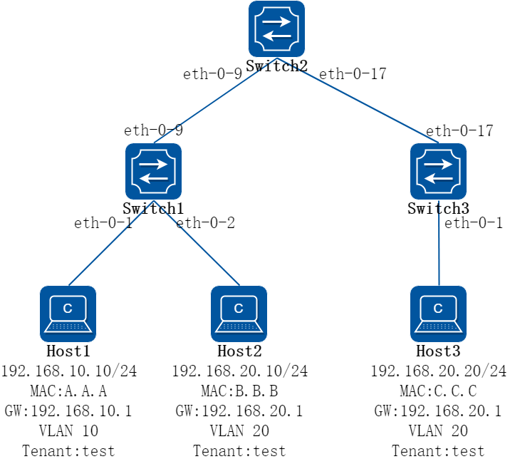
图17-13集中式VXLAN网关组网图
2.组网需求
如图所示,HOST1、2、3都属于租户test,其间既有相同网段又有不同网段,且都需要相互通信。Switch 1、2、3之间为三层网络,因此需要通过配置VXLAN在HOST之间建立隧道,并通过集中式网关来实现HOST之间的通信。
![]() 可以将SWITCH 2作为集中式网关。
可以将SWITCH 2作为集中式网关。
3.配置步骤
步骤 1分别在SWITCH 1、SWITCH 2、SWITCH 3上配置路由,保证交换机之间三层网络可通
配置SWITCH 1
SWITCH_1# configure terminal
Enter configuration commands, one per line. End with CNTL/Z.
SWITCH_1(config)# interface loopback 0
SWITCH_1(config-if)# ip address 10.1.1.1/32
SWITCH_1(config-if)# exit
SWITCH_1(config)# interface eth-0-9
SWITCH_1(config-if)# no switchport
SWITCH_1(config-if)# ip address 192.168.9.1/24
SWITCH_1(config-if)# no shutdown
SWITCH_1(config-if)# exit
SWITCH_1(config)# ip route 10.2.2.2/32 192.168.9.2
SWITCH_1(config)# ip route 10.3.3.3/32 192.168.9.2
SWITCH_1(config)# end
配置SWITCH 2
SWITCH_2# configure terminal
Enter configuration commands, one per line. End with CNTL/Z.
SWITCH_2(config)# interface loopback 0
SWITCH_2(config-if)# ip address 10.2.2.2/32
SWITCH_2(config-if)# exit
SWITCH_2(config)# interface eth-0-9
SWITCH_2(config-if)# no switchport
SWITCH_2(config-if)# ip address 192.168.9.2/24
SWITCH_2(config-if)# no shutdown
SWITCH_2(config-if)# exit
SWITCH_2(config)# interface eth-0-17
SWITCH_2(config-if)# no switchport
SWITCH_2(config-if)# ip address 192.168.17.2/24
SWITCH_2(config-if)# no shutdown
SWITCH_2(config-if)# exit
SWITCH_2(config)# ip route 10.3.3.3/32 192.168.17.1
SWITCH_2(config)# ip route 10.1.1.1/32 192.168.9.1
SWITCH_2(config)# end
配置SWITCH 3
SWITCH_3# configure terminal
Enter configuration commands, one per line. End with CNTL/Z.
SWITCH_3(config)# interface loopback 0
SWITCH_3(config-if)# ip address 10.3.3.3/32
SWITCH_3(config-if)# exit
SWITCH_3(config)# interface eth-0-17
SWITCH_3(config-if)# no switchport
SWITCH_3(config-if)# ip address 192.168.17.1/24
SWITCH_3(config-if)# no shutdown
SWITCH_3(config-if)# exit
SWITCH_3(config)# ip route 10.1.1.1/32 192.168.17.2
SWITCH_3(config)# ip route 10.2.2.2/32 192.168.17.2
SWITCH_3(config)# end
步骤 2分别在SWITCH 1、SWITCH 2、SWITCH 3上配置VLAN
配置SWITCH 1
SWITCH_1# configure terminal
Enter configuration commands, one per line. End with CNTL/Z.
SWITCH_1(config)# vlan database
SWITCH_1(config-vlan)# vlan 10,20
SWITCH_1(config-vlan)# vlan 10 overlay enable
SWITCH_1(config-vlan)# vlan 20 overlay enable
SWITCH_1(config-vlan)# exit
SWITCH_1(config)# interface eth-0-1
SWITCH_1(config-if)# switchport mode access
SWITCH_1(config-if)# switchport access vlan 10
SWITCH_1(config-if)# no shutdown
SWITCH_1(config-if)# exit
SWITCH_1(config)# interface eth-0-2
SWITCH_1(config-if)# switchport mode access
SWITCH_1(config-if)# switchport access vlan 20
SWITCH_1(config-if)# no shutdown
SWITCH_1(config-if)# end
配置SWITCH 2
SWITCH_2# configure terminal
Enter configuration commands, one per line. End with CNTL/Z.
SWITCH_2(config)# vlan database
SWITCH_2(config-vlan)# vlan 10,20
SWITCH_2(config-vlan)# vlan 10 overlay enable
SWITCH_2(config-vlan)# vlan 20 overlay enable
SWITCH_2(config-vlan)# end
配置SWITCH 3
SWITCH_3# configure terminal
Enter configuration commands, one per line. End with CNTL/Z.
SWITCH_3(config)# vlan database
SWITCH_3(config-vlan)# vlan 20
SWITCH_3(config-vlan)# vlan 20 overlay enable
SWITCH_3(config-vlan)# exit
SWITCH_3(config)# interface eth-0-1
SWITCH_3(config-if)# switchport mode access
SWITCH_3(config-if)# switchport access vlan 20
SWITCH_3(config-if)# no shutdown
SWITCH_3(config-if)# end
步骤 3在SWITCH 1、SWITCH 2、SWITCH 3间建立VXLAN隧道
配置SWITCH 1
SWITCH_1# configure terminal
Enter configuration commands, one per line. End with CNTL/Z.
SWITCH_1(config)# interface eth-0-9
SWITCH_1(config-if)# vxlan uplink enable
SWITCH_1(config-if)# exit
SWITCH_1(config)# overlay
SWITCH_1(config-overlay)# source 10.1.1.1
SWITCH_1(config-overlay)# remote-vtep 1 ip-address 10.2.2.2 type vxlan
SWITCH_1(config-overlay)# remote-vtep 2 ip-address 10.3.3.3 type vxlan
SWITCH_1(config-overlay)# vlan 10 vni 10000
SWITCH_1(config-overlay)# vlan 10 remote-vtep 1
SWITCH_1(config-overlay)# vlan 20 vni 20000
SWITCH_1(config-overlay)# vlan 20 remote-vtep 1
SWITCH_1(config-overlay)# vlan 20 remote-vtep 2
SWITCH_1(config-overlay)# end
配置SWITCH 2
SWITCH_2# configure terminal
Enter configuration commands, one per line. End with CNTL/Z.
SWITCH_2(config)# interface eth-0-9
SWITCH_2(config-if)# vxlan uplink enable
SWITCH_2(config-if)# exit
SWITCH_2(config)# interface eth-0-17
SWITCH_2(config-if)# vxlan uplink enable
SWITCH_2(config-if)# exit
SWITCH_2(config)# overlay
SWITCH_2(config-overlay)# source 10.2.2.2
SWITCH_2(config-overlay)# remote-vtep 1 ip-address 10.1.1.1 type vxlan
SWITCH_2(config-overlay)# remote-vtep 2 ip-address 10.3.3.3 type vxlan
SWITCH_2(config-overlay)# vlan 10 vni 10000
SWITCH_2(config-overlay)# vlan 10 remote-vtep 1
SWITCH_2(config-overlay)# vlan 20 vni 20000
SWITCH_2(config-overlay)# vlan 20 remote-vtep 1
SWITCH_2(config-overlay)# vlan 20 remote-vtep 2
SWITCH_2(config-overlay)# end
配置SWITCH 3
SWITCH_3# configure terminal
Enter configuration commands, one per line. End with CNTL/Z.
SWITCH_3(config)# interface eth-0-17
SWITCH_3(config-if)# vxlan uplink enable
SWITCH_3(config-if)# exit
SWITCH_3(config)# overlay
SWITCH_3(config-overlay)# source 10.3.3.3
SWITCH_3(config-overlay)# remote-vtep 1 ip-address 10.1.1.1 type vxlan
SWITCH_3(config-overlay)# remote-vtep 2 ip-address 10.2.2.2 type vxlan
SWITCH_3(config-overlay)# vlan 20 vni 20000
SWITCH_3(config-overlay)# vlan 20 remote-vtep 1
SWITCH_3(config-overlay)# vlan 20 remote-vtep 2
SWITCH_3(config-overlay)# end
步骤 4分别在SWITCH 2上配置相应HOST的网关,绑定到相应VRF下。
配置SWITCH 2
SWITCH_2# configure terminal
Enter configuration commands, one per line. End with CNTL/Z.
SWITCH_2(config)# ip vrf test
SWITCH_2(config-vrf)# exit
SWITCH_2(config)# interface vlan 10
SWITCH_2(config-if)# ip vrf forwarding test
SWITCH_2(config-if)# ip address 192.168.10.1/24
SWITCH_2(config-if)# exit
SWITCH_2(config)# interface vlan 20
SWITCH_2(config-if)# ip vrf forwarding test
SWITCH_2(config-if)# ip address 192.168.20.2/24
SWITCH_2(config-if)# end
至此配置已经完成,HOST 1/2/4之间应可以相互ping通。
![]() 此处举例中的VRF是为了隔离不同租户,如无需要可以不配置VRF。
此处举例中的VRF是为了隔离不同租户,如无需要可以不配置VRF。
步骤 5检查配置
检查底层网络是否互通
SWITCH_1# ping -a 10.1.1.1 10.2.2.2
PING 10.2.2.2 (10.2.2.2) from 10.1.1.1 : 56(84) bytes of data.
64 bytes from 10.2.2.2: icmp_seq=1 ttl=64 time=2.57 ms
64 bytes from 10.2.2.2: icmp_seq=2 ttl=64 time=2.05 ms
64 bytes from 10.2.2.2: icmp_seq=3 ttl=64 time=2.29 ms
64 bytes from 10.2.2.2: icmp_seq=4 ttl=64 time=2.07 ms
64 bytes from 10.2.2.2: icmp_seq=5 ttl=64 time=2.44 ms
--- 10.2.2.2 ping statistics ---
5 packets transmitted, 5 received, 0% packet loss, time 4004ms
rtt min/avg/max/mdev = 2.059/2.287/2.573/0.210 ms
SWITCH_1# ping -a 10.1.1.1 10.3.3.3
PING 10.3.3.3 (10.3.3.3) from 10.1.1.1 : 56(84) bytes of data.
64 bytes from 10.3.3.3: icmp_seq=1 ttl=63 time=3.32 ms
64 bytes from 10.3.3.3: icmp_seq=2 ttl=63 time=2.45 ms
64 bytes from 10.3.3.3: icmp_seq=3 ttl=63 time=2.50 ms
64 bytes from 10.3.3.3: icmp_seq=4 ttl=63 time=2.42 ms
64 bytes from 10.3.3.3: icmp_seq=5 ttl=63 time=3.49 ms
--- 10.3.3.3 ping statistics ---
5 packets transmitted, 5 received, 0% packet loss, time 4004ms
rtt min/avg/max/mdev = 2.421/2.839/3.491/0.467 ms
检查隧道配置是否正确
SWITCH_2# show overlay
-------------------------------------------------------------------------------
ECMP Mode : Normal
Source VTEP : 10.1.1.1
Vlan Vni Type Remote-vtep IP-Address Src-Address Head-end-flooding Protocol
-------------------------------------------------------------------------------
10 10000 VxLAN 1 10.2.2.2 10.1.1.1 Enable Static
20 20000 VxLAN 1 10.2.2.2 10.1.1.1 Enable Static
20 20000 VxLAN 2 10.3.3.3 10.1.1.1 Enable Static
SWITCH_1# show overlay uplink
-------------------------------------------------------------------------------
Uplink port:
eth-0-9
-------------------------------------------------------------------------------S
检查SWITCH 2(gateway)上ARP
SWITCH_2 # show ip arp
Protocol Address Age (min) Hardware Addr Interface
Internet 192.168.9.2 - 001e.081b.bce0 eth-0-9
Internet 192.168.9.1 0 001e.080a.a7fb eth-0-9
Internet 192.168.17.2 - 001e.081b.bce0 eth-0-17
Internet 192.168.17.1 0 001e.081f.13bc eth-0-17
Internet 192.168.10.10 0 001e.080c.46ce vlan10(tunnel)
Internet 192.168.20.10 0 001e.0811.05f9 vlan20(tunnel)
Internet 192.168.10.1 - 001e.081b.bce0 vlan10
Internet 192.168.20.1 - 001e.081b.bce0 vlan20
Internet 192.168.20.20 0 001e.080c.755e vlan20(tunnel)
17.1.3部署建议
双活接入VXLAN网络及分布式网关综合示例
1.组网拓扑
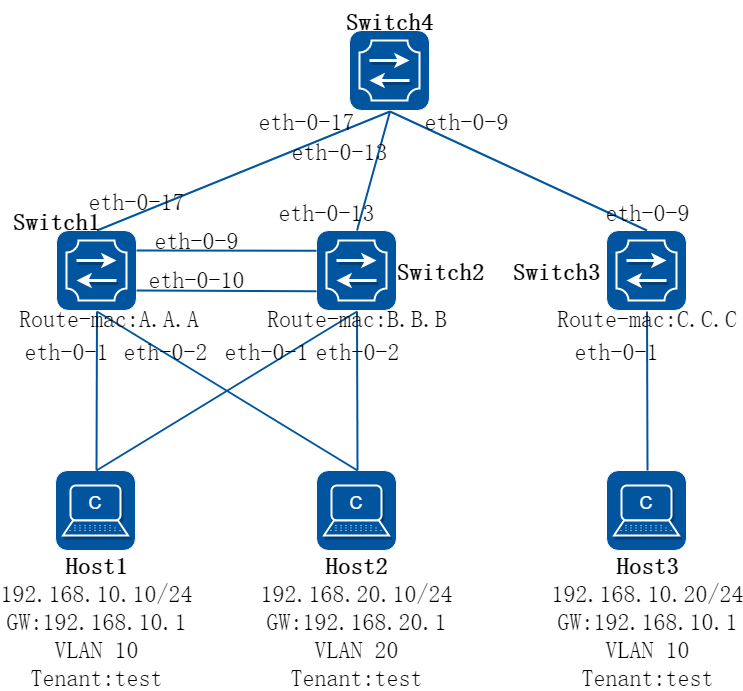
图17-14双活接入VXLAN网络及分布式网关组网图
2.组网需求
如图所示,Switch 1、2、3作为TOR交换机,其间网络为三层网络,下联的HOST都属于租户test,需求与其他租户隔离。为了保证可靠性,其中部分服务器需要双活接入,因此需要在SWITCH 1、2上配置MLAG并配置virtual ip作为服务器网关。同时为了保证虚拟机迁移后网关地址不变,在SWITCH 1、2、3上部署分布式网关。
3.配置步骤
步骤 1分别在SWITCH 1、2配置MLAG,用于服务器双活接入,SWITCH 3使用单接口下联
配置peer-link
配置SWITCH 1
SWITCH_1# configure terminal
Enter configuration commands, one per line. End with CNTL/Z.
SWITCH_1 (config)# interface range eth-0-9 to eth-0-10
SWITCH_1(config-if-range)# no shutdown
SWITCH_1 (config-if-range)# channel-group 55 mode active
SWITCH_1 (config-if-range)# exit
SWITCH_1 (config)# interface agg 55
SWITCH_1 (config-if)# switchport mode trunk
SWITCH_1 (config-if)# switchport trunk allowed vlan all
SWITCH_1 (config-if)# spanning-tree port disable
SWITCH_1 (config-if)# exit
SWITCH_1 (config)# no ip igmp snooping
SWITCH_1 (config)# mlag configuration
SWITCH_1 (config-mlag)# peer-link agg 55
SWITCH_1 (config-mlag)# end
配置SWITCH 2
SWITCH_2# configure terminal
Enter configuration commands, one per line. End with CNTL/Z.
SWITCH_2(config)# interface range eth-0-9 to eth-0-10
SWITCH_2(config-if-range)# no shutdown
SWITCH_2(config-if-range)# channel-group 55 mode active
SWITCH_2(config-if-range)# exit
SWITCH_2(config)# interface agg 55
SWITCH_2(config-if)# switchport mode trunk
SWITCH_2(config-if)# switchport trunk allowed vlan all
SWITCH_2(config-if)# spanning-tree port disable
SWITCH_2(config-if)# exit
SWITCH_2(config)# mlag configuration
SWITCH_2(config-mlag)# peer-link agg 55
SWITCH_2(config-mlag)# end
配置peer-address
配置SWITCH 1
SWITCH_1# configure terminal
Enter configuration commands, one per line. End with CNTL/Z.
SWITCH_1(config)# vlan database
SWITCH_1(config-vlan)# vlan 4094
SWITCH_1(config-vlan)# exit
SWITCH_1(config)# interface vlan 4094
SWITCH_1(config-if)# ip address 40.94.0.1/24
SWITCH_1(config-if)# exit
SWITCH_1(config)# mlag configuration
SWITCH_1(config-mlag)# peer-address 40.94.0.2
SWITCH_1(config-mlag)# end
配置SWITCH 2
SWITCH_2# configure terminal
Enter configuration commands, one per line. End with CNTL/Z.
SWITCH_2(config)# vlan database
vSWITCH_2(config-vlan)# vlan 4094
SWITCH_2(config-vlan)# exit
SWITCH_2(config)# interface vlan 4094
SWITCH_2(config-if)# ip address 40.94.0.2/24
SWITCH_2(config-if)# exit
SWITCH_2(config)# no ip igmp snooping
SWITCH_2(config)# mlag configuration
SWITCH_2(config-mlag)# peer-address 40.94.0.1
SWITCH_2(config-mlag)# end
配置下联接口,SWITCH 1、2使用MLAG双下联,SWITCH 3普通单下联
配置SWITCH 1
SWITCH_1# configure terminal
Enter configuration commands, one per line. End with CNTL/Z.
SWITCH_1(config)# vlan database
SWITCH_1(config-vlan)# vlan 10,20,100
SWITCH_1(config-vlan)# exit
SWITCH_1(config)# interface eth-0-1
SWITCH_1(config-if)# switchport mode trunk
SWITCH_1(config-if)# switchport trunk allowed vlan add 10
SWITCH_1(config-if)# no shutdown
SWITCH_1(config-if)# static-channel-group 1
SWITCH_1(config-if)# exit
SWITCH_1(config)# interface eth-0-2
SWITCH_1(config-if)# switchport mode trunk
SWITCH_1(config-if)# switchport trunk allowed vlan add 20
SWITCH_1(config-if)# no shutdown
SWITCH_1(config-if)# static-channel-group 2
SWITCH_1(config-if)# exit
SWITCH_1(config)# interface agg 1
SWITCH_1(config-if)# mlag 1
SWITCH_1(config-if)# exit
SWITCH_1(config)# interface agg 2
SWITCH_1(config-if)# mlag 2
SWITCH_1(config-if)# end
配置SWITCH 2
SWITCH_2# configure terminal
Enter configuration commands, one per line. End with CNTL/Z.
SWITCH_2(config)# vlan database
SWITCH_2(config-vlan)# vlan 10,20,100
SWITCH_2(config-vlan)# exit
SWITCH_2(config)# interface eth-0-1
SWITCH_2(config-if)# switchport mode trunk
SWITCH_2(config-if)# switchport trunk allowed vlan add 10
SWITCH_2(config-if)# static-channel-group 1
SWITCH_2(config-if)# no shutdown
SWITCH_2(config-if)# exit
SWITCH_2(config)# interface eth-0-2
SWITCH_2(config-if)# switchport mode trunk
SWITCH_2(config-if)# switchport trunk allowed vlan add 20
SWITCH_2(config-if)# static-channel-group 2
SWITCH_2(config-if)# no shutdown
SWITCH_2(config-if)# exit
SWITCH_2(config)# interface agg 1
SWITCH_2(config-if)# mlag 1
SWITCH_2(config-if)# exit
SWITCH_2(config)# interface agg 2
SWITCH_2(config-if)# mlag 2
SWITCH_2(config-if)# end
配置SWITCH 3
SWITCH_3# configure terminal
Enter configuration commands, one per line. End with CNTL/Z.
SWITCH_3(config)# vlan database
SWITCH_3(config-vlan)# vlan 10
SWITCH_3(config-vlan)# exit
SWITCH_3(config)# interface eth-0-1
SWITCH_3(config-if)# switchport mode trunk
SWITCH_3(config-if)# switchport trunk allowed vlan add 10
SWITCH_3(config-if)# no shutdown
SWITCH_3(config-if)# end
步骤 2配置网关地址并使能分布式网关,在MLAG设备上使用virtual ip
配置SWITCH 1
SWITCH_1# configure terminal
Enter configuration commands, one per line. End with CNTL/Z.
SWITCH_1(config)# ip vrf test
SWITCH_1(config-vrf)# exit
SWITCH_1(config)# interface vlan 10
SWITCH_1(config-if)# ip vrf forwarding test
SWITCH_1(config-if)# ip address 192.168.10.253/24
SWITCH_1(config-if)# ip virtual-router address 192.168.10.1
SWITCH_1(config-if)# overlay distributed-gateway enable
SWITCH_1(config-if)# exit
SWITCH_1(config)# interface vlan 20
SWITCH_1(config-if)# ip vrf forwarding test
SWITCH_1(config-if)# ip address 192.168.20.253/24
SWITCH_1(config-if)# ip virtual-router address 192.168.20.1
SWITCH_1(config-if)# overlay distributed-gateway enable
SWITCH_1(config-if)# exit
SWITCH_1(config)# ip virtual-router mac 0.0.1
SWITCH_1(config)# interface vlan 100
SWITCH_1(config-if)# end
配置SWITCH 2
SWITCH_2# configure terminal
Enter configuration commands, one per line. End with CNTL/Z.
SWITCH_2(config)# ip vrf test
SWITCH_2(config-vrf)# exit
SWITCH_2(config)# interface vlan 10
SWITCH_2(config-if)# ip vrf forwarding test
SWITCH_2(config-if)# ip address 192.168.10.254/24
SWITCH_2(config-if)# ip virtual-router address 192.168.10.1
SWITCH_2(config-if)# overlay distributed-gateway enable
SWITCH_2(config-if)# exit
SWITCH_2(config)# interface vlan 20
SWITCH_2(config-if)# ip vrf forwarding test
SWITCH_2(config-if)# ip address 192.168.20.254/24
SWITCH_2(config-if)# ip virtual-router address 192.168.20.1
SWITCH_2(config-if)# overlay distributed-gateway enable
SWITCH_2(config-if)# exit
SWITCH_2(config)# ip virtual-router mac 0.0.1
SWITCH_2(config)# interface vlan 100
SWITCH_2(config)# end
配置SWITCH 3
SWITCH_3# configure terminal
Enter configuration commands, one per line. End with CNTL/Z.
SWITCH_3(config)# ip vrf test
SWITCH_3(config-vrf)# exit
SWITCH_3(config)# interface vlan 10
SWITCH_3(config-if)# ip vrf forwarding test
SWITCH_3(config-if)# ip address 192.168.10.1/24
SWITCH_3(config-if)# overlay distributed-gateway enable
SWITCH_3(config-if)# end
步骤 3配置SWITCH之间的三层网络
配置SWITCH 1
SWITCH_1# configure terminal
Enter configuration commands, one per line. End with CNTL/Z.
SWITCH_1(config)# interface loopback 0
SWITCH_1(config-if)# ip address 10.1.1.1/32
SWITCH_1(config-if)# exit
SWITCH_1(config)# interface eth-0-17
SWITCH_1(config-if)# no switchport
SWITCH_1(config-if)# no shutdown
SWITCH_1(config-if)# ip address 192.168.17.1/24
SWITCH_1(config-if)# exit
SWITCH_1(config)# ip route 10.3.3.3/32 192.168.17.2
SWITCH_1(config)# ip route 10.3.3.3/32 40.94.0.2 100
SWITCH_1(config)#end
配置SWITCH 2
SWITCH_2# configure terminal
Enter configuration commands, one per line. End with CNTL/Z.
SWITCH_2(config)# interface loopback 0
SWITCH_2(config-if)# ip address 10.1.1.1/32
SWITCH_2(config-if)# exit
SWITCH_2(config)# interface eth-0-13
SWITCH_2(config-if)# no switchport
SWITCH_2(config-if)# no shutdown
SWITCH_2(config-if)# ip address 192.168.13.1/24
SWITCH_2(config-if)# exit
SWITCH_2(config)# ip route 10.3.3.3/32 192.168.13.2
SWITCH_2(config)# ip route 10.3.3.3/32 40.94.0.1 100
SWITCH_2(config)# end
配置SWITCH 3
SWITCH_3# configure terminal
Enter configuration commands, one per line. End with CNTL/Z.
SWITCH_3(config)# interface loopback 0
SWITCH_3(config-if)# ip address 10.3.3.3/32
SWITCH_3(config-if)# exit
SWITCH_3(config)# interface eth-0-9
SWITCH_3(config-if)# no shutdown
SWITCH_3(config-if)# no switchport
SWITCH_3(config-if)# ip address 192.168.9.1/24
SWITCH_3(config-if)# exit
SWITCH_3(config)# ip route 10.1.1.1/32 192.168.9.2
SWITCH_3(config)# end
配置SWITCH 4
SWITCH_4# configure terminal
Enter configuration commands, one per line. End with CNTL/Z.
SWITCH_4(config)# interface eth-0-17
SWITCH_4(config-if)# no shutdown
SWITCH_4(config-if)# no switchport
SWITCH_4(config-if)# ip address 192.168.17.2/24
SWITCH_4(config-if)# exit
SWITCH_4(config)# interface eth-0-13
SWITCH_4(config-if)# no shutdown
SWITCH_4(config-if)# no switchport
SWITCH_4(config-if)# ip address 192.168.13.2/24
SWITCH_4(config-if)# exit
SWITCH_4(config)# interface eth-0-9
SWITCH_4(config-if)# no shutdown
SWITCH_4(config-if)# no switchport
SWITCH_4(config-if)# ip address 192.168.9.2/24
SWITCH_4(config-if)# exit
SWITCH_4(config)# ip route 10.1.1.1/32 192.168.17.1
SWITCH_4(config)# ip route 10.1.1.1/32 192.168.13.1
SWITCH_4(config)# ip route 10.3.3.3/32 192.168.9.1
SWITCH_4(config)# end
步骤 4配置VXLAN隧道
配置SWITCH 1
SWITCH_1# configure terminal
Enter configuration commands, one per line. End with CNTL/Z.
SWITCH_1(config)# vlan database
SWITCH_1(config-vlan)# vlan 10 overlay enable
SWITCH_1(config-vlan)# vlan 100 overlay enable
SWITCH_1(config-vlan)# exit
SWITCH_1(config)# overlay
SWITCH_1(config-overlay)# source 10.1.1.1
SWITCH_1(config-overlay)# remote-vtep 1 ip-address 10.3.3.3 type vxlan
SWITCH_1(config-overlay)# vlan 10 vni 10000
SWITCH_1(config-overlay)# vlan 10 remote-vtep 1
SWITCH_1(config-overlay)# vlan 100 vni 100
SWITCH_1(config-overlay)# vlan 100 remote-vtep 1
SWITCH_1(config-overlay)# exit
SWITCH_1(config)# interface eth-0-17
SWITCH_1(config-if)# vxlan uplink enable
SWITCH_1(config-if)# end
配置SWITCH 2
SWITCH_2# configure terminal
Enter configuration commands, one per line. End with CNTL/Z.
SWITCH_2(config)# vlan database SWITCH_B(config-vlan)# vlan 10 overlay enable
SWITCH_2(config-vlan)# vlan 100 overlay enable
SWITCH_2(config-vlan)# exit
SWITCH_2(config)# overlay
SWITCH_2(config-overlay)# source 10.1.1.1
SWITCH_2(config-overlay)# remote-vtep 1 ip-address 10.3.3.3 type vxlan
SWITCH_2(config-overlay)# vlan 10 vni 10000
SWITCH_2(config-overlay)# vlan 10 remote-vtep 1
SWITCH_2(config-overlay)# vlan 100 vni 100
SWITCH_2(config-overlay)# vlan 100 remote-vtep 1
SWITCH_2(config-overlay)# exit
SWITCH_2(config)# interface eth-0-13
SWITCH_2(config-if)# vxlan uplink enable
SWITCH_2(config-if)# end
配置SWITCH 3
SWITCH_3# configure terminal
Enter configuration commands, one per line. End with CNTL/Z.
SWITCH_3(config)# vlan database
SWITCH_3(config-vlan)# vlan 10,100
SWITCH_3(config-vlan)# vlan 10 overlay enable
SWITCH_3(config-vlan)# vlan 100 overlay enable
SWITCH_3(config-vlan)# exit
SWITCH_3(config)# overlay
SWITCH_3(config-overlay)# source 10.3.3.3
SWITCH_3(config-overlay)# remote-vtep 1 ip-address 10.1.1.1 type vxlan
SWITCH_3(config-overlay)# vlan 10 vni 10000
SWITCH_3(config-overlay)# vlan 10 remote-vtep 1
SWITCH_3(config-overlay)# vlan 100 vni 100
SWITCH_3(config-overlay)# vlan 100 remote-vtep 1
SWITCH_3(config-overlay)# exit
SWITCH_3(config)# interface eth-0-9
SWITCH_3(config-if)# vxlan uplink enable
SWITCH_3(config-if)# end
步骤 5配置DVR路由,使分布在不同SWITCH下的不同网段主机可以互通
配置SWITCH 1
SWITCH_1# configure terminal
Enter configuration commands, one per line. End with CNTL/Z.
SWITCH_1(config)# ip route vrf test 192.168.10.20/32 remote-vtep 1 vni 100 inner-macda c.c.c
SWITCH_1(config)# end
配置SWITCH 2
SWITCH_2# configure terminal
Enter configuration commands, one per line. End with CNTL/Z.
SWITCH_2(config)# ip route vrf test 192.168.10.20/32 remote-vtep 1 vni 100 inner-macda c.c.c
SWITCH_2(config)# end
配置SWITCH 3
SWITCH_3# configure terminal
Enter configuration commands, one per line. End with CNTL/Z.
SWITCH_3(config)# ip route vrf test 192.168.20.10/32 remote-vtep 1 vni 100 inner-macda 0.0.1
SWITCH_3(config)# end
步骤 6检查配置
查看MLAG状态
SWITCH_1# show mlag peer
MLAG neighbor is 40.94.0.2, MLAG version 1
MLAG state = Established, up for 23:41:26
Last read 00:00:42, hold time is 240, keepalive interval is 60 seconds
Received 1652 messages,Sent 1654 messages
Open : received 1, sent 2
KAlive : received 1646, sent 1646
Fdb sync : received 0, sent 0
Failover : received 0, sent 0
Conf : received 2, sent 2
Syspri : received 1, sent 1
Peer fdb : received 15, sent 15
STP Total: received 2, sent 3
Global : received 2, sent 3
Packet : received 0, sent 0
Instance: received 0, sent 0
State : received 0, sent 0
Connections established 1; dropped 0
Local host: 40.94.0.1, Local port: 61000
Foreign host: 40.94.0.2, Foreign port: 42371
remote_sysid: 06a8.c402.0300
查看MLAG下联接口状态
SWITCH_1# show mlag interface
mlagid local-if local-state remote-state
1 agg1 up up
2 agg2 up up
查看VXLAN状态
SWITCH_1# show overlay
---------------------------------------------------------------
ECMP Mode : Normal
Source VTEP : 10.1.1.1
Vlan Vni Type Remote-vtep IP-Address
---------------------------------------------------------------
10 10000 VxLAN 1 10.3.3.3
100 100 VxLAN 1 10.3.3.3
查看DVR路由是否生效
SWITCH_1# show ip route vrf test
Codes: K - kernel, C - connected, S - static, R - RIP, B - BGP
O - OSPF, IA - OSPF inter area
N1 - OSPF NSSA external type 1, N2 - OSPF NSSA external type 2
E1 - OSPF external type 1, E2 - OSPF external type 2
i - IS-IS, L1 - IS-IS level-1, L2 - IS-IS level-2, ia - IS-IS inter area
Dc - DHCP Client
[*] - [AD/Metric]
* - candidate default
C 192.168.10.0/24 is directly connected, vlan10
C 192.168.10.253/32 is in local loopback, vlan10
C 192.168.10.1/32 is directly connected, vlan10
S 192.168.10.20/32 is in overlay remote vxlan vtep:10.3.3.3, vni:100
C 192.168.20.0/24 is directly connected, vlan20
C 192.168.20.253/32 is in local loopback, vlan20
C 192.168.20.1/32 is directly connected, vlan20
17.2.1概述
简介
NVGRE是一种利用通用路由封装的网络虚拟化技术,能够将虚拟网络承载在物理网络之上。NVGRE使用GRE的封装形式,利用GRE头的低24bit来代表虚拟网络ID(VNI),类似VXLAN一样24bit的ID可以允许1600百万个虚拟网络。
17.2.2配置举例
配置NVGRE
1.组网拓扑

图17-15NVGRE
2.配置步骤
在下面的配置举例中,通过NVGRE技术,将两台设备上vlan 20的流量封装在vni 20000中实现互联互通。
以下配置如未说明在哪个Switch配置,则表示所有Switch配置相同:
步骤 1进入配置模式
Switch# configure terminal
步骤 2进入vlan配置模式并创建vlan,在vlan上使能overlay
Switch(config)# vlan database
Switch(config-vlan)# vlan 20
Switch(config-vlan)# vlan 20 overlay enable
Switch(config-vlan)# exit
步骤 3进入接口配置模式,配置接口属性
Switch1 的接口配置:
Switch1(config)# interface eth-0-1
Switch1(config-if)# switchport access vlan 20
Switch1(config-if)# no shutdown
Switch1(config-if)# exit
Switch1(config)# interface eth-0-2
Switch1(config-if)# switchport mode trunk
Switch1(config-if)# switchport trunk allowed vlan add 20
Switch1(config-if)# no shutdown
Switch1(config-if)# exit
Switch1(config)# interface eth-0-9
Switch1(config-if)# no switchport
Switch1(config-if)# ip address 9.9.9.1/24
Switch1(config-if)# overlay uplink enable
Switch1(config-if)# no shutdown
Switch1(config-if)# exit
Switch1(config)# interface loopback0
Switch1(config-if)# ip address 1.0.1.1/32
Switch1(config-if)# exit
Switch2 的接口配置:
Switch2(config)# interface eth-0-1
Switch2(config-if)# switchport access vlan 20
Switch2(config-if)# no shutdown
Switch2(config-if)# exit
Switch2(config)# interface eth-0-2
Switch2(config-if)# switchport mode trunk
Switch2(config-if)# switchport trunk allowed vlan add 20
Switch2(config-if)# no shutdown
Switch2(config-if)# exit
Switch2(config)# interface eth-0-9
Switch2(config-if)# no switchport
Switch2(config-if)# ip address 9.9.9.2/24
Switch2(config-if)# overlay uplink enable
Switch2(config-if)# no shutdown
Switch2(config-if)# exit
Switch2(config)# interface loopback0
Switch2(config-if)# ip address 1.0.1.2/32
Switch2(config-if)# exit
步骤 4配置静态路由
在switch1配置:
Switch1(config)# ip route 1.0.1.2/32 9.9.9.2
在switch2配置:
Switch2(config)# ip route 1.0.1.1/32 9.9.9.1
步骤 5配置overlay
在switch1配置:
Switch1(config)# overlay
Switch1(config-overlay)# source 1.0.1.1
Switch1(config-overlay)# remote-vtep 1 ip-address 1.0.1.2 type nvgre
Switch1(config-overlay)# vlan 20 vni 20000
Switch1(config-overlay)# vlan 20 remote-vtep 1
Switch1(config-overlay)# exit
在switch2配置:
Switch2(config)# overlay
Switch2(config-overlay)# source 1.0.1.2
Switch2(config-overlay)# remote-vtep 1 ip-address 1.0.1.1 type nvgre
Switch2(config-overlay)# vlan 20 vni 20000
Switch2(config-overlay)# vlan 20 remote-vtep 1
Switch2(config-overlay)# exit
步骤 6退出配置模式
Switch(config)# end
步骤 7检查配置
Switch1 显示结果:
Switch1# show overlay vlan 20
-------------------------------------------------------------------------------
ECMP Mode : Normal
Source VTEP : 1.0.1.1
-------------------------------------------------------------------------------
VLAN ID : 20
VNI : 20000
EVPN Tunnel Data-fdb Learning : Enable
Remote VTEP NUM : 1
Index: 1, Ip address: 1.0.1.2, Source ip: 1.0.1.1, Type: NvGRE, Protocol: Static
DVR Gateway NUM: 0
-------------------------------------------------------------------------
Switch2 显示结果:
Switch2# show overlay vlan 20
-------------------------------------------------------------------------------
ECMP Mode : Normal
Source VTEP : 1.0.1.2
-------------------------------------------------------------------------------
VLAN ID : 20
VNI : 20000
EVPN Tunnel Data-fdb Learning : Eanble
Remote VTEP NUM : 1
Index: 1, Ip address: 1.0.1.1, Source ip: 1.0.1.2, Type: NvGRE, Protocol: Static
DVR Gateway NUM: 0
-------------------------------------------------------------------------------
NVGRE分布式路由配置
1.组网拓扑

图17-16NVGRE 分布式路由
2.配置步骤
在下面的配置举例中,按上图所示,VM-1和VM-3在同一个VNI中,通过NVGRE互联建立分布式路由;VM-2和VM-4在同一个VNI中,通过NVGRE互联建立分布式路由。
以下配置如未说明在哪个Switch配置,则表示所有Switch配置相同:
步骤 1进入配置模式
Switch# configure terminal
步骤 2进入vlan配置模式并创建vlan,在vlan上使能overlay
Switch(config)# vlan database
Switch(config-vlan)# vlan 20,30
Switch(config-vlan)# vlan 20 overlay enable
Switch(config-vlan)# vlan 30 overlay enable
Switch(config-vlan)# exit
步骤 3创建vrf实例
Switch(config)# ip vrf tenant
Switch(config-vrf)# exit
步骤 4创建三层接口,加入vrf并配置地址
在switch1配置:
Switch1(config)# interface vlan 20
Switch1(config-if)# ip vrf forwarding tenant
Switch1(config-if)# ip address 2.2.2.111/24
Switch1(config-if)# exit
Switch1(config)# interface vlan 30
Switch1(config-if)# ip vrf forwarding tenant
Switch1(config-if)# ip address 3.3.3.111/24
Switch1(config-if)# exit
在switch2配置:
Switch2(config)# interface vlan 20
Switch2(config-if)# ip vrf forwarding tenant
Switch2(config-if)# ip address 2.2.2.222/24
Switch2(config-if)# exit
Switch2(config)# interface vlan 30
Switch2(config-if)# ip vrf forwarding tenant
Switch2(config-if)# ip address 3.3.3.222/24
Switch2(config-if)# exit
步骤 5进入接口配置模式,配置接口属性
Switch(config)# interface eth-0-1
Switch(config-if)# switchport mode trunk
Switch(config-if)# switchport trunk allowed vlan add 20
Switch(config-if)# no shutdown
Switch(config-if)# exit
Switch(config)# interface eth-0-2
Switch(config-if)# switchport mode trunk
Switch(config-if)# switchport trunk allowed vlan add 30
Switch(config-if)# no shutdown
Switch(config-if)# exit
在switch1配置:
Switch1(config)# interface eth-0-9
Switch1(config-if)# no switchport
Switch1(config-if)# ip address 9.9.9.1/24
Switch1(config-if)# overlay uplink enable
Switch1(config-if)# no shutdown
Switch1(config-if)# exit
Switch1(config)# interface loopback0
Switch1(config-if)# ip address 1.0.1.1/32
Switch1(config-if)# exit
在switch2配置:
Switch2(config)# interface eth-0-9
Switch2(config-if)# no switchport
Switch2(config-if)# ip address 9.9.9.2/24
Switch2(config-if)# overlay uplink enable
Switch2(config-if)# no shutdown
Switch2(config-if)# exit
Switch2(config)# interface loopback0
Switch2(config-if)# ip address 1.0.1.2/32
Switch2(config-if)# exit
步骤 6配置overlay
在switch1配置:
Switch1(config)# overlay
Switch1(config-overlay)# source 1.0.1.1
Switch1(config-overlay)# remote-vtep 1 ip-address 1.0.1.2 type nvgre
Switch1(config-overlay)# remote-vtep 1 virtual-mac 22.22.22
Switch1(config-overlay)# vlan 20 vni 20000
Switch1(config-overlay)# vlan 30 vni 30000
Switch1(config-overlay)# vlan 20 remote-vtep 1
Switch1(config-overlay)# vlan 30 remote-vtep 1
Switch1(config-overlay)# vlan 20 gateway-mac a.a.a
Switch1(config-overlay)# vlan 30 gateway-mac b.b.b
Switch1(config-overlay)# exit
在switch2配置:
Switch2(config)# overlay
Switch2(config-overlay)# source 1.0.1.2
Switch2(config-overlay)# remote-vtep 1 ip-address 1.0.1.1 type nvgre
Switch2(config-overlay)# remote-vtep 1 virtual-mac 11.11.11
Switch2(config-overlay)# vlan 20 vni 20000
Switch2(config-overlay)# vlan 30 vni 30000
Switch2(config-overlay)# vlan 20 remote-vtep 1
Switch2(config-overlay)# vlan 30 remote-vtep 1
Switch2(config-overlay)# vlan 20 gateway-mac a.a.a
Switch2(config-overlay)# vlan 30 gateway-mac b.b.b
Switch2(config-overlay)# exit
步骤 7配置静态路由和nvgre分布式路由
在switch1配置:
Switch1(config)# ip route 1.0.1.2/32 9.9.9.2
Switch1(config)# ip route vrf tenant 2.2.2.2/32 remote-vtep 1 vni 20000 inner-macda 3.3.3
Switch1(config)# ip route vrf tenant 3.3.3.2/32 remote-vtep 1 vni 30000 inner-macda 4.4.4
在switch2配置:
Switch2(config)# ip route 1.0.1.1/32 9.9.9.1
Switch2(config)# ip route vrf tenant 2.2.2.1/32 remote-vtep 1 vni 20000 inner-macda 1.1.1
Switch2(config)# ip route vrf tenant 3.3.3.1/32 remote-vtep 1 vni 30000 inner-macda 2.2.2
步骤 8退出配置模式
Switch(config)# end
步骤 9检查配置
Switch1 显示结果:
Switch1# show ip route vrf tenant
Codes: K - kernel, C - connected, S - static, R - RIP, B - BGP
O - OSPF, IA - OSPF inter area
N1 - OSPF NSSA external type 1, N2 - OSPF NSSA external type 2
E1 - OSPF external type 1, E2 - OSPF external type 2
i - IS-IS, L1 - IS-IS level-1, L2 - IS-IS level-2, ia - IS-IS inter area
Dc - DHCP Client
[*] - [AD/Metric]
* - candidate default
S 2.2.2.2/32 is in overlay remote nvgre vtep:1.0.1.1->1.0.1.2, vni:20000
S 3.3.3.2/32 is in overlay remote nvgre vtep:1.0.1.1->1.0.1.2, vni:30000
Switch2 显示结果:
Switch2# show ip route vrf tenant
Codes: K - kernel, C - connected, S - static, R - RIP, B - BGP
O - OSPF, IA - OSPF inter area
N1 - OSPF NSSA external type 1, N2 - OSPF NSSA external type 2
E1 - OSPF external type 1, E2 - OSPF external type 2
i - IS-IS, L1 - IS-IS level-1, L2 - IS-IS level-2, ia - IS-IS inter area
Dc - DHCP Client
[*] - [AD/Metric]
* - candidate default
S 2.2.2.1/32 is in overlay remote nvgre vtep:1.0.1.2->1.0.1.1, vni:20000
S 3.3.3.1/32 is in overlay remote nvgre vtep:1.0.1.2->1.0.1.1, vni:30000
基于IPv6网络配置NvGRE
1.组网拓扑

图17-17IPv6 NVGRE
2.配置步骤
在下面的配置举例中,通过NVGRE技术,将两台设备上vlan 20的流量封装在vni 20000中实现互联互通。
以下配置如未说明在哪个Switch配置,则表示所有Switch配置相同:
步骤 1进入配置模式
Switch# configure terminal
步骤 2进入vlan配置模式并创建vlan,在vlan上使能overlay
Switch(config)# vlan database
Switch(config-vlan)# vlan 20
Switch(config-vlan)# vlan 20 overlay enable
Switch(config-vlan)# exit
步骤 3进入接口配置模式,配置接口属性
Switch1 的接口配置:
Switch1(config)# ipv6 enable
Switch1(config)# interface eth-0-1
Switch1(config-if)# switchport access vlan 20
Switch1(config-if)# no shutdown
Switch1(config-if)# exit
Switch1(config)# interface eth-0-2
Switch1(config-if)# switchport mode trunk
Switch1(config-if)# switchport trunk allowed vlan add 20
Switch1(config-if)# no shutdown
Switch1(config-if)# exit
Switch1(config)# interface eth-0-9
Switch1(config-if)# no switchport
Switch1(config-if)# ipv6 address 2000::1/64
Switch1(config-if)# nvgre uplink enable
Switch1(config-if)# no shutdown
Switch1(config-if)# exit
Switch1(config)# interface loopback0
Switch1(config-if)# ipv6 address 1111::1/128
Switch1(config-if)# exit
Switch2 的接口配置:
Switch2(config)# interface eth-0-1
Switch2(config-if)# switchport access vlan 20
Switch2(config-if)# no shutdown
Switch2(config-if)# exit
Switch2(config)# interface eth-0-2
Switch2(config-if)# switchport mode trunk
Switch2(config-if)# switchport trunk allowed vlan add 20
Switch2(config-if)# no shutdown
Switch2(config-if)# exit
Switch2(config)# interface eth-0-9
Switch2(config-if)# no switchport
Switch2(config-if)# ipv6 address 2000::2/64
Switch2(config-if)# nvgre uplink enable
Switch2(config-if)# no shutdown
Switch2(config-if)# exit
Switch2(config)# interface loopback0
Switch2(config-if)# ipv6 address 2222::2/128
Switch2(config-if)# exit
步骤 4配置静态路由
在switch1配置:
Switch1(config)# ipv6 route 2222::2/128 2000::2
在switch2配置:
Switch2(config)# ipv6 route 1111::1/128 2000::1
步骤 5配置overlay
在switch1配置:
Switch1(config)# overlay
Switch1(config-overlay)# source 1111::1
Switch1(config-overlay)# remote-vtep 1 ipv6-address 2222::2 type nvgre
Switch1(config-overlay)# vlan 20 vni 20000
Switch1(config-overlay)# vlan 20 remote-vtep 1
Switch1(config-overlay)# exit
在switch2配置:
Switch2(config)# overlay
Switch2(config-overlay)# source 2222::2
Switch2(config-overlay)# remote-vtep 1 ipv6-address 2222::2 type nvgre
Switch2(config-overlay)# vlan 20 vni 20000
Switch2(config-overlay)# vlan 20 remote-vtep 1
Switch2(config-overlay)# exit
步骤 6退出配置模式
Switch(config)# end
步骤 7检查配置
Switch1 显示结果:
Switch1# show overlay vlan 20
-------------------------------------------------------------------------------
ECMP Mode : Normal
Source VTEP : 1111::1
-------------------------------------------------------------------------------
VLAN ID : 20
VNI : 20000
EVPN Tunnel Data-fdb Learning : Enable
Remote VTEP NUM : 1
Index: 1, Type: NvGRE, Protocol: Static
IP address: 2222::2
Source ip : 1111::1
DVR Gateway NUM: 0
-------------------------------------------------------------------------
Switch2 显示结果:
Switch2# show overlay vlan 20
-------------------------------------------------------------------------------
ECMP Mode : Normal
Source VTEP : 2222::2
-------------------------------------------------------------------------------
VLAN ID : 20
VNI : 20000
EVPN Tunnel Data-fdb Learning : Enable
Remote VTEP NUM : 1
Index: 1, Type: NvGRE, Protocol: Static
IP address: 1111::1
Source ip : 2222::2
DVR Gateway NUM: 0
-------------------------------------------------------------------------
基于IPv6配置NvGRE分布式路由
1.组网拓扑

图17-18IPv6 NVGRE 分布式路由
2.配置步骤
在下面的配置举例中,按上图所示,VM-1和VM-3在同一个VNI中,通过NVGRE互联建立分布式路由;VM-2和VM-4在同一个VNI中,通过NVGRE互联建立分布式路由。
以下配置如未说明在哪个Switch配置,则表示所有Switch配置相同:
步骤 1进入配置模式
Switch# configure terminal
步骤 2进入vlan配置模式并创建vlan,在vlan上使能overlay
Switch(config)# vlan database
Switch(config-vlan)# vlan 20,30
Switch(config-vlan)# vlan 20 overlay enable
Switch(config-vlan)# vlan 30 overlay enable
Switch(config-vlan)# exit
步骤 3创建vrf实例
Switch(config)# ip vrf tenant
Switch(config-vrf)# exit
步骤 4创建三层接口,加入vrf并配置地址
在switch1配置:
Switch1(config)# ipv6 enable
Switch1(config)# interface vlan 20
Switch1(config-if)# ip vrf forwarding tenant
Switch1(config-if)# ipv6 address 2000::111/64
Switch1(config-if)# exit
Switch1(config)# interface vlan 30
Switch1(config-if)# ip vrf forwarding tenant
Switch1(config-if)# ipv6 address 3000::111/64
Switch1(config-if)# exit
在switch2配置:
Switch2(config)# interface vlan 20
Switch2(config-if)# ip vrf forwarding tenant
Switch2(config-if)# ipv6 address 2000::222/24
Switch2(config-if)# exit
Switch2(config)# interface vlan 30
Switch2(config-if)# ip vrf forwarding tenant
Switch2(config-if)# ipv6 address 3000::222/24
Switch2(config-if)# exit
步骤 5进入接口配置模式,配置接口属性
Switch(config)# interface eth-0-1
Switch(config-if)# switchport mode trunk
Switch(config-if)# switchport trunk allowed vlan add 20
Switch(config-if)# no shutdown
Switch(config-if)# exit
Switch(config)# interface eth-0-2
Switch(config-if)# switchport mode trunk
Switch(config-if)# switchport trunk allowed vlan add 30
Switch(config-if)# no shutdown
Switch(config-if)# exit
在switch1配置:
Switch1(config)# interface eth-0-9
Switch1(config-if)# no switchport
Switch1(config-if)# ipv6 address 1234::1/64
Switch1(config-if)# nvgre uplink enable
Switch1(config-if)# no shutdown
Switch1(config-if)# exit
Switch1(config)# interface loopback0
Switch1(config-if)# ipv6 address 1111::1/128
Switch1(config-if)# exit
在switch2配置:
Switch2(config)# interface eth-0-9
Switch2(config-if)# no switchport
Switch2(config-if)# ipv6 address 1234::2/64
Switch2(config-if)# nvgre uplink enable
Switch2(config-if)# no shutdown
Switch2(config-if)# exit
Switch2(config)# interface loopback0
Switch2(config-if)# ipv6 address 2222::2/128
Switch2(config-if)# exit
步骤 6配置overlay
在switch1配置:
Switch1(config)# overlay
Switch1(config-overlay)# source 1111::1
Switch1(config-overlay)# remote-vtep 1 ipv6-address 2222::2 type nvgre
Switch1(config-overlay)# vlan 20 vni 20000
Switch1(config-overlay)# vlan 30 vni 30000
Switch1(config-overlay)# vlan 20 remote-vtep 1
Switch1(config-overlay)# vlan 30 remote-vtep 1
Switch1(config-overlay)# vlan 20 gateway-mac a.a.a
Switch1(config-overlay)# vlan 30 gateway-mac b.b.b
Switch1(config-overlay)# exit
在switch2配置:
Switch2(config)# overlay
Switch2(config-overlay)# source 2222::2
Switch2(config-overlay)# remote-vtep 1 ipv6-address 1111::1 type nvgre
Switch2(config-overlay)# vlan 20 vni 20000
Switch2(config-overlay)# vlan 30 vni 30000
Switch2(config-overlay)# vlan 20 remote-vtep 1
Switch2(config-overlay)# vlan 30 remote-vtep 1
Switch2(config-overlay)# vlan 20 gateway-mac a.a.a
Switch2(config-overlay)# vlan 30 gateway-mac b.b.b
Switch2(config-overlay)# exit
步骤 7配置静态路由和NVGRE分布式路由
在switch1配置:
Switch1(config)# ipv6 route 2222::2/128 1234::2
Switch1(config)# ipv6 route vrf tenant 2000::2/128 remote-vtep 1 vni 20000 inner-macda 3.3.3
Switch1(config)# ipv6 route vrf tenant 3000::2/128 remote-vtep 1 vni 30000 inner-macda 4.4.4
在switch2配置:
Switch2(config)# ipv6 route 1111::1/128 1234::1
Switch2(config)# ipv6 route vrf tenant 2000::1/32 remote-vtep 1 vni 20000 inner-macda 1.1.1
Switch2(config)# ipv6 route vrf tenant 3000::1/32 remote-vtep 1 vni 30000 inner-macda 2.2.2
步骤 8退出配置模式
Switch(config)# end
步骤 9检查配置
Switch1 显示结果:
Switch1# show ipv6 route vrf tenant
Codes: C - connected, S - static, R - RIP, I - IS-IS, B - BGP
O - OSPF, IA - OSPF inter area
N1 - OSPF NSSA external type 1, N2 - OSPF NSSA external type 2
E1 - OSPF external type 1, E2 - OSPF external type 2
Dr - DHCPV6 Relay
[*] - [AD/Metric]
S 2000::2/128 is in overlay remote nvgre vtep:1111::1->2222::2, vni:20000
S 3000::2/128 is in overlay remote nvgre vtep:1111::1->2222::2, vni:30000
Switch2 显示结果:
Switch2# show ipv6 route vrf tenant
Codes: C - connected, S - static, R - RIP, I - IS-IS, B - BGP
O - OSPF, IA - OSPF inter area
N1 - OSPF NSSA external type 1, N2 - OSPF NSSA external type 2
E1 - OSPF external type 1, E2 - OSPF external type 2
Dr - DHCPV6 Relay
[*] - [AD/Metric]
S 2000::1/128 is in overlay remote nvgre vtep:2222::2->1111::1, vni:20000
S 3000::1/128 is in overlay remote nvgre vtep:2222::2->1111::1, vni:30000
17.3.1概述
简介
通用网络虚拟化封装(GENEVE)是一种隧道网络技术,其将基于mac的2层以太网数据报文封装在3层UDP的数据报文中,通过3层路由网络实现承载在3层网络上的2层网络通信。GENEVE技术把逻辑网络的数量扩大到1600万个,并且支持异地跨ip的2层互联以及可扩展的option。
17.3.2配置举例
配置GENEVE
1.组网拓扑

图17-19GENEVE
2.配置步骤
在下面的配置举例中,switch1和switch2间有三层路由联通,通过GENEVE技术,将两台设备上vlan 20的流量封装在vni 20000中,从而实现互联互通。
以下配置如未说明在哪个Switch配置,则表示所有Switch配置相同:
步骤 1进入配置模式
Switch# configure terminal
步骤 2进入vlan配置模式并创建vlan,在vlan上使能overlay
Switch(config)# vlan database
Switch(config-vlan)# vlan 20
Switch(config-vlan)# vlan 20 overlay enable
Switch(config-vlan)# exit
步骤 3进入接口配置模式,配置接口属性
Switch1 的接口配置:
Switch1(config)# interface eth-0-1
Switch1(config-if)# switchport access vlan 20
Switch1(config-if)# no shutdown
Switch1(config-if)# exit
Switch1(config)# interface eth-0-2
Switch1(config-if)# switchport mode trunk
Switch1(config-if)# switchport trunk allowed vlan add 20
Switch1(config-if)# no shutdown
Switch1(config-if)# exit
Switch1(config)# interface eth-0-9
Switch1(config-if)# no switchport
Switch1(config-if)# ip address 9.9.9.1/24
Switch1(config-if)# vxlan uplink enable
Switch1(config-if)# no shutdown
Switch1(config-if)# exit
Switch1(config)# interface loopback0
Switch1(config-if)# ip address 1.0.1.1/32
Switch1(config-if)# exit
Switch2 的接口配置:
Switch2(config)# interface eth-0-1
Switch2(config-if)# switchport access vlan 20
Switch2(config-if)# no shutdown
Switch2(config-if)# exit
Switch2(config)# interface eth-0-2
Switch2(config-if)# switchport mode trunk
Switch2(config-if)# switchport trunk allowed vlan add 20
Switch2(config-if)# no shutdown
Switch2(config-if)# exit
Switch2(config)# interface eth-0-9
Switch2(config-if)# no switchport
Switch2(config-if)# ip address 9.9.9.2/24
Switch2(config-if)# vxlan uplink enable
Switch2(config-if)# no shutdown
Switch2(config-if)# exit
Switch2(config)# interface loopback0
Switch2(config-if)# ip address 1.0.1.2/32
Switch2(config-if)# exit
步骤 4配置静态路由
在switch1配置:
Switch1(config)# ip route 1.0.1.2/32 9.9.9.2
在switch2配置:
Switch2(config)# ip route 1.0.1.1/32 9.9.9.1
步骤 5配置overlay
在switch1配置:
Switch1(config)# overlay
Switch1(config-overlay)# source 1.0.1.1
Switch1(config-overlay)# remote-vtep 1 ip-address 1.0.1.2 type geneve
Switch1(config-overlay)# vlan 20 vni 20000
Switch1(config-overlay)# vlan 20 remote-vtep 1
Switch1(config-overlay)# exit
在switch2配置:
Switch2(config)# overlay
Switch2(config-overlay)# source 1.0.1.2
Switch2(config-overlay)# remote-vtep 1 ip-address 1.0.1.1 type geneve
Switch2(config-overlay)# vlan 20 vni 20000
Switch2(config-overlay)# vlan 20 remote-vtep 1
Switch2(config-overlay)# exit
步骤 6退出配置模式
Switch(config)# end
步骤 7检查配置
Switch1 显示结果:
Switch1# show overlay vlan 20
-------------------------------------------------------------------------------
ECMP Mode : Normal
Source VTEP : 1.0.1.1
-------------------------------------------------------------------------------
VLAN ID : 20
VNI : 20000
EVPN Tunnel Data-fdb Learning : Enable
Remote VTEP NUM : 1
Index: 1, Ip address: 1.0.1.2, Source ip: 1.0.1.1, Type: GENEVE, Protocol: Static
DVR Gateway NUM: 0
-------------------------------------------------------------------------
Switch2 显示结果:
Switch2# show overlay vlan 20
-------------------------------------------------------------------------------
ECMP Mode : Normal
Source VTEP : 1.0.1.2
-------------------------------------------------------------------------------
VLAN ID : 20
VNI : 20000
EVPN Tunnel Data-fdb Learning : Eanble
Remote VTEP NUM : 1
Index: 1, Ip address: 1.0.1.1, Source ip: 1.0.1.2, Type: GENEVE, Protocol: Static
DVR Gateway NUM: 0
-------------------------------------------------------------------------------
配置GENEVE分布式路由
1.组网拓扑
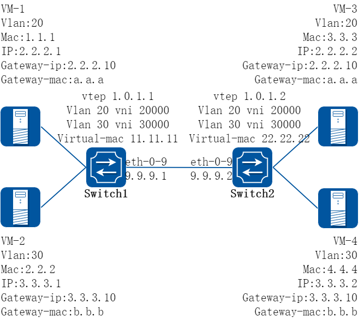
图17-20GENEVE 分布式路由
2.配置步骤
在下面的配置举例中,按上图所示,VM-1和VM-3在同一个VNI中,通过GENEVE互联建立分布式路由;VM-2和VM-4在同一个VNI中,通过GENEVE互联建立分布式路由。
以下配置如未说明在哪个Switch配置,则表示所有Switch配置相同:
步骤 1进入配置模式
Switch# configure terminal
步骤 2进入vlan配置模式并创建vlan,在vlan上使能overlay
Switch(config)# vlan database
Switch(config-vlan)# vlan 20,30
Switch(config-vlan)# vlan 20 overlay enable
Switch(config-vlan)# vlan 30 overlay enable
Switch(config-vlan)# exit
步骤 3创建vrf实例
Switch(config)# ip vrf tenant
Switch(config-vrf)# exit
步骤 4创建三层接口,加入vrf并配置地址
在switch1配置:
Switch1(config)# interface vlan 20
Switch1(config-if)# ip vrf forwarding tenant
Switch1(config-if)# ip address 2.2.2.111/24
Switch1(config-if)# exit
Switch1(config)# interface vlan 30
Switch1(config-if)# ip vrf forwarding tenant
Switch1(config-if)# ip address 3.3.3.111/24
Switch1(config-if)# exit
在switch2配置:
Switch2(config)# interface vlan 20
Switch2(config-if)# ip vrf forwarding tenant
Switch2(config-if)# ip address 2.2.2.222/24
Switch2(config-if)# exit
Switch2(config)# interface vlan 30
Switch2(config-if)# ip vrf forwarding tenant
Switch2(config-if)# ip address 3.3.3.222/24
Switch2(config-if)# exit
步骤 5进入接口配置模式,配置接口属性
Switch(config)# interface eth-0-1
Switch(config-if)# switchport mode trunk
Switch(config-if)# switchport trunk allowed vlan add 20
Switch(config-if)# no shutdown
Switch(config-if)# exit
Switch(config)# interface eth-0-2
Switch(config-if)# switchport mode trunk
Switch(config-if)# switchport trunk allowed vlan add 30
Switch(config-if)# no shutdown
Switch(config-if)# exit
在switch1配置:
Switch1(config)# interface eth-0-9
Switch1(config-if)# no switchport
Switch1(config-if)# ip address 9.9.9.1/24
Switch1(config-if)# overlay uplink enable
Switch1(config-if)# no shutdown
Switch1(config-if)# exit
Switch1(config)# interface loopback0
Switch1(config-if)# ip address 1.0.1.1/32
Switch1(config-if)# exit
在switch2配置:
Switch2(config)# interface eth-0-9
Switch2(config-if)# no switchport
Switch2(config-if)# ip address 9.9.9.2/24
Switch2(config-if)# overlay uplink enable
Switch2(config-if)# no shutdown
Switch2(config-if)# exit
Switch2(config)# interface loopback0
Switch2(config-if)# ip address 1.0.1.2/32
Switch2(config-if)# exit
步骤 6配置overlay
在switch1配置:
Switch1(config)# overlay
Switch1(config-overlay)# source 1.0.1.1
Switch1(config-overlay)# remote-vtep 1 ip-address 1.0.1.2 type geneve
Switch1(config-overlay)# remote-vtep 1 virtual-mac 22.22.22
Switch1(config-overlay)# vlan 20 vni 20000
Switch1(config-overlay)# vlan 30 vni 30000
Switch1(config-overlay)# vlan 20 remote-vtep 1
Switch1(config-overlay)# vlan 30 remote-vtep 1
Switch1(config-overlay)# vlan 20 gateway-mac a.a.a
Switch1(config-overlay)# vlan 30 gateway-mac b.b.b
Switch1(config-overlay)# exit
在switch2配置:
Switch2(config)# overlay
Switch2(config-overlay)# source 1.0.1.2
Switch2(config-overlay)# remote-vtep 1 ip-address 1.0.1.1 type geneve
Switch2(config-overlay)# remote-vtep 1 virtual-mac 11.11.11
Switch2(config-overlay)# vlan 20 vni 20000
Switch2(config-overlay)# vlan 30 vni 30000
Switch2(config-overlay)# vlan 20 remote-vtep 1
Switch2(config-overlay)# vlan 30 remote-vtep 1
Switch2(config-overlay)# vlan 20 gateway-mac a.a.a
Switch2(config-overlay)# vlan 30 gateway-mac b.b.b
Switch2(config-overlay)# exit
步骤 7配置静态路由和GENEVE分布式路由
在switch1配置:
Switch1(config)# ip route 1.0.1.2/32 9.9.9.2
Switch1(config)# ip route vrf tenant 2.2.2.2/32 remote-vtep 1 vni 20000 inner-macda 3.3.3
Switch1(config)# ip route vrf tenant 3.3.3.2/32 remote-vtep 1 vni 30000 inner-macda 4.4.4
在switch2配置:
Switch2(config)# ip route 1.0.1.1/32 9.9.9.1
Switch2(config)# ip route vrf tenant 2.2.2.1/32 remote-vtep 1 vni 20000 inner-macda 1.1.1
Switch2(config)# ip route vrf tenant 3.3.3.1/32 remote-vtep 1 vni 30000 inner-macda 2.2.2
步骤 8退出配置模式
Switch(config)# end
步骤 9检查配置
Switch1 显示结果:
switch1# show ip route vrf tenant
Codes: K - kernel, C - connected, S - static, R - RIP, B - BGP
O - OSPF, IA - OSPF inter area
N1 - OSPF NSSA external type 1, N2 - OSPF NSSA external type 2
E1 - OSPF external type 1, E2 - OSPF external type 2
i - IS-IS, L1 - IS-IS level-1, L2 - IS-IS level-2, ia - IS-IS inter area
Dc - DHCP Client
[*] - [AD/Metric]
* - candidate default
S 2.2.2.2/32 is in overlay remote geneve vtep:1.0.1.1->1.0.1.2, vni:20000
S 3.3.3.2/32 is in overlay remote geneve vtep:1.0.1.1->1.0.1.2, vni:30000
Switch2 显示结果:
switch2# show ip route vrf tenant
Codes: K - kernel, C - connected, S - static, R - RIP, B - BGP
O - OSPF, IA - OSPF inter area
N1 - OSPF NSSA external type 1, N2 - OSPF NSSA external type 2
E1 - OSPF external type 1, E2 - OSPF external type 2
i - IS-IS, L1 - IS-IS level-1, L2 - IS-IS level-2, ia - IS-IS inter area
Dc - DHCP Client
[*] - [AD/Metric]
* - candidate default
S 2.2.2.1/32 is in overlay remote geneve vtep:1.0.1.2->1.0.1.1, vni:20000
S 3.3.3.1/32 is in overlay remote geneve vtep:1.0.1.2->1.0.1.1, vni:30000
基于IPv6网络配置GENEVE
1.组网拓扑

图17-21IPv6 GENEVE
2.配置步骤
在下面的配置举例中,switch1和switch2间三层路由联通,通过GENEVE技术,将两台设备上vlan 20的流量封装在vni 20000中,从而实现跨越三层网络的互联互通。
以下配置如未说明在哪个Switch配置,则表示所有Switch配置相同:
步骤 1进入配置模式
Switch# configure terminal
步骤 2进入vlan配置模式并创建vlan,在vlan上使能overlay
Switch(config)# vlan database
Switch(config-vlan)# vlan 20
Switch(config-vlan)# vlan 20 overlay enable
Switch(config-vlan)# exit
步骤 3进入接口配置模式,配置接口属性
Switch1 的接口配置:
Switch1(config)# ipv6 enable
Switch1(config)# interface eth-0-1
Switch1(config-if)# switchport access vlan 20
Switch1(config-if)# no shutdown
Switch1(config-if)# exit
Switch1(config)# interface eth-0-2
Switch1(config-if)# switchport mode trunk
Switch1(config-if)# switchport trunk allowed vlan add 20
Switch1(config-if)# no shutdown
Switch1(config-if)# exit
Switch1(config)# interface eth-0-9
Switch1(config-if)# no switchport
Switch1(config-if)# ipv6 address 2000::1/64
Switch1(config-if)# vxlan uplink enable
Switch1(config-if)# no shutdown
Switch1(config-if)# exit
Switch1(config)# interface loopback0
Switch1(config-if)# ipv6 address 1111::1/128
Switch1(config-if)# exit
Switch2 的接口配置:
Switch2(config)# interface eth-0-1
Switch2(config-if)# switchport access vlan 20
Switch2(config-if)# no shutdown
Switch2(config-if)# exit
Switch2(config)# interface eth-0-2
Switch2(config-if)# switchport mode trunk
Switch2(config-if)# switchport trunk allowed vlan add 20
Switch2(config-if)# no shutdown
Switch2(config-if)# exit
Switch2(config)# interface eth-0-9
Switch2(config-if)# no switchport
Switch2(config-if)# ipv6 address 2000::2/64
Switch2(config-if)# vxlan uplink enable
Switch2(config-if)# no shutdown
Switch2(config-if)# exit
Switch2(config)# interface loopback0
Switch2(config-if)# ipv6 address 2222::2/128
Switch2(config-if)# exit
步骤 4配置静态路由
在switch1配置:
Switch1(config)# ipv6 route 2222::2/128 2000::2
在switch2配置:
Switch2(config)# ipv6 route 1111::1/128 2000::1
步骤 5配置overlay
在switch1配置:
Switch1(config)# overlay
Switch1(config-overlay)# source 1111::1
Switch1(config-overlay)# remote-vtep 1 ipv6-address 2222::2 type geneve
Switch1(config-overlay)# vlan 20 vni 20000
Switch1(config-overlay)# vlan 20 remote-vtep 1
Switch1(config-overlay)# exit
在switch2配置:
Switch2(config)# overlay
Switch2(config-overlay)# source 2222::2
Switch2(config-overlay)# remote-vtep 1 ipv6-address 2222::2 type geneve
Switch2(config-overlay)# vlan 20 vni 20000
Switch2(config-overlay)# vlan 20 remote-vtep 1
Switch2(config-overlay)# exit
步骤 6退出配置模式
Switch(config)# end
步骤 7检查配置
Switch1 显示结果:
Switch1# show overlay vlan 20
-------------------------------------------------------------------------------
ECMP Mode : Normal
Source VTEP : 1111::1
-------------------------------------------------------------------------------
VLAN ID : 20
VNI : 20000
EVPN Tunnel Data-fdb Learning : Enable
Remote VTEP NUM : 1
Index: 1, Type: GENEVE, Protocol: Static
IP address: 2222::2
Source ip : 1111::1
DVR Gateway NUM: 0
-------------------------------------------------------------------------
Switch2 显示结果:
Switch2# show overlay vlan 20
-------------------------------------------------------------------------------
ECMP Mode : Normal
Source VTEP : 2222::2
-------------------------------------------------------------------------------
VLAN ID : 20
VNI : 20000
EVPN Tunnel Data-fdb Learning : Enable
Remote VTEP NUM : 1
Index: 1, Type: GENEVE, Protocol: Static
IP address: 1111::1
Source ip : 2222::2
DVR Gateway NUM: 0
-------------------------------------------------------------------------
基于IPv6配置GENEVE分布式路由
1.组网拓扑
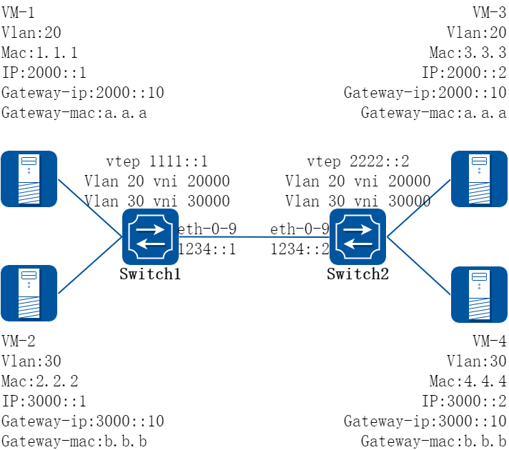
图17-22IPv6 GENEVE 分布式路由
2.配置步骤
在下面的配置举例中,按上图所示,VM-1和VM-3在同一个VNI中,通过GENEVE互联建立分布式路由;VM-2和VM-4在同一个VNI中,通过GENEVE互联建立分布式路由。
以下配置如未说明在哪个Switch配置,则表示所有Switch配置相同:
步骤 1进入配置模式
Switch# configure terminal
步骤 2进入vlan配置模式并创建vlan,在vlan上使能overlay
Switch(config)# vlan database
Switch(config-vlan)# vlan 20,30
Switch(config-vlan)# vlan 20 overlay enable
Switch(config-vlan)# vlan 30 overlay enable
Switch(config-vlan)# exit
步骤 3创建vrf实例
Switch(config)# ip vrf tenant
Switch(config-vrf)# exit
步骤 4创建三层接口,加入vrf并配置地址
在switch1配置:
Switch1(config)# ipv6 enable
Switch1(config)# interface vlan 20
Switch1(config-if)# ip vrf forwarding tenant
Switch1(config-if)# ipv6 address 2000::111/64
Switch1(config-if)# exit
Switch1(config)# interface vlan 30
Switch1(config-if)# ip vrf forwarding tenant
Switch1(config-if)# ipv6 address 3000::111/64
Switch1(config-if)# exit
在switch2配置:
Switch2(config)# interface vlan 20
Switch2(config-if)# ip vrf forwarding tenant
Switch2(config-if)# ipv6 address 2000::222/24
Switch2(config-if)# exit
Switch2(config)# interface vlan 30
Switch2(config-if)# ip vrf forwarding tenant
Switch2(config-if)# ipv6 address 3000::222/24
Switch2(config-if)# exit
步骤 5进入接口配置模式,配置接口属性
Switch(config)# interface eth-0-1
Switch(config-if)# switchport mode trunk
Switch(config-if)# switchport trunk allowed vlan add 20
Switch(config-if)# no shutdown
Switch(config-if)# exit
Switch(config)# interface eth-0-2
Switch(config-if)# switchport mode trunk
Switch(config-if)# switchport trunk allowed vlan add 30
Switch(config-if)# no shutdown
Switch(config-if)# exit
在switch1配置:
Switch1(config)# interface eth-0-9
Switch1(config-if)# no switchport
Switch1(config-if)# ipv6 address 1234::1/64
Switch1(config-if)# vxlan uplink enable
Switch1(config-if)# no shutdown
Switch1(config-if)# exit
Switch1(config)# interface loopback0
Switch1(config-if)# ipv6 address 1111::1/128
Switch1(config-if)# exit
在switch2配置:
Switch2(config)# interface eth-0-9
Switch2(config-if)# no switchport
Switch2(config-if)# ipv6 address 1234::2/64
Switch2(config-if)# vxlan uplink enable
Switch2(config-if)# no shutdown
Switch2(config-if)# exit
Switch2(config)# interface loopback0
Switch2(config-if)# ipv6 address 2222::2/128
Switch2(config-if)# exit
步骤 6配置overlay
在switch1配置:
Switch1(config)# overlay
Switch1(config-overlay)# source 1111::1
Switch1(config-overlay)# remote-vtep 1 ipv6-address 2222::2 type geneve
Switch1(config-overlay)# vlan 20 vni 20000
Switch1(config-overlay)# vlan 30 vni 30000
Switch1(config-overlay)# vlan 20 remote-vtep 1
Switch1(config-overlay)# vlan 30 remote-vtep 1
Switch1(config-overlay)# vlan 20 gateway-mac a.a.a
Switch1(config-overlay)# vlan 30 gateway-mac b.b.b
Switch1(config-overlay)# exit
在switch2配置:
Switch2(config)# overlay
Switch2(config-overlay)# source 2222::2
Switch2(config-overlay)# remote-vtep 1 ipv6-address 1111::1 type geneve
Switch2(config-overlay)# vlan 20 vni 20000
Switch2(config-overlay)# vlan 30 vni 30000
Switch2(config-overlay)# vlan 20 remote-vtep 1
Switch2(config-overlay)# vlan 30 remote-vtep 1
Switch2(config-overlay)# vlan 20 gateway-mac a.a.a
Switch2(config-overlay)# vlan 30 gateway-mac b.b.b
Switch2(config-overlay)# exit
步骤 7配置静态路由和geneve分布式路由
在switch1配置:
Switch1(config)# ipv6 route 2222::2/128 1234::2
Switch1(config)# ipv6 route vrf tenant 2000::2/128 remote-vtep 1 vni 20000 inner-macda 3.3.3
Switch1(config)# ipv6 route vrf tenant 3000::2/128 remote-vtep 1 vni 30000 inner-macda 4.4.4
在switch2配置:
Switch2(config)# ipv6 route 1111::1/128 1234::1
Switch2(config)# ipv6 route vrf tenant 2000::1/32 remote-vtep 1 vni 20000 inner-macda 1.1.1
Switch2(config)# ipv6 route vrf tenant 3000::1/32 remote-vtep 1 vni 30000 inner-macda 2.2.2
步骤 8退出配置模式
Switch(config)# end
步骤 9检查配置
Switch1 显示结果:
Switch1# show ipv6 route vrf tenant
Codes: C - connected, S - static, R - RIP, I - IS-IS, B - BGP
O - OSPF, IA - OSPF inter area
N1 - OSPF NSSA external type 1, N2 - OSPF NSSA external type 2
E1 - OSPF external type 1, E2 - OSPF external type 2
Dr - DHCPV6 Relay
[*] - [AD/Metric]
S 2000::2/128 is in overlay remote geneve vtep:1111::1->2222::2, vni:20000
S 3000::2/128 is in overlay remote geneve vtep:1111::1->2222::2, vni:30000
Switch2 显示结果:
Switch2# show ipv6 route vrf tenant
Codes: C - connected, S - static, R - RIP, I - IS-IS, B - BGP
O - OSPF, IA - OSPF inter area
N1 - OSPF NSSA external type 1, N2 - OSPF NSSA external type 2
E1 - OSPF external type 1, E2 - OSPF external type 2
Dr - DHCPV6 Relay
[*] - [AD/Metric]
S 2000::1/128 is in overlay remote geneve vtep:2222::2->1111::1, vni:20000
S 3000::1/128 is in overlay remote geneve vtep:2222::2->1111::1, vni:30000
17.4.1概述
简介
Overlay支持多上联,是为了满足用户针对不同的公网而设定不同的source ip地址,提高overlay 的可靠性。
Overlay也支持tunnel上关闭水平分割,即允许报文进入uplink 口解封装后,再次进入另外的tunnel进行加封装发送报文。
17.4.2配置举例
Overlay支持多上联配置
1.组网拓扑
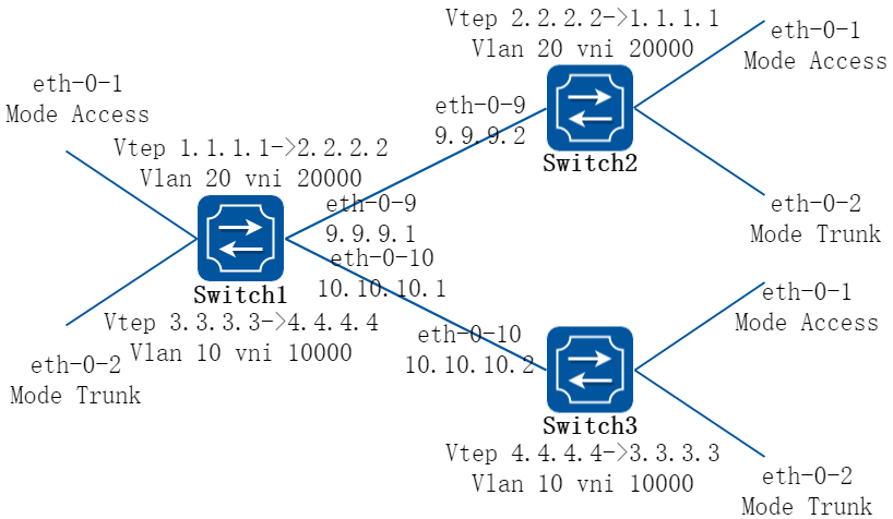
图17-23Overlay multiple source ip
2.配置步骤
在下面的配置举例中,以VXLAN 为例。NVGRE和GENEVE的配置类似。
以下配置如未说明在哪个Switch配置,则表示所有Switch配置相同:
步骤 1进入配置模式
Switch# configure terminal
步骤 2进入vlan配置模式并创建vlan,在vlan上使能overlay
在switch1配置:
Switch1(config)# vlan database
Switch1(config-vlan)# vlan 20,10
Switch1(config-vlan)# vlan 20 overlay enable
Switch1(config-vlan)# vlan 10 overlay enable
Switch1(config-vlan)# exit
在switch2配置:
Switch2(config)# vlan database
Switch2(config-vlan)# vlan 20
Switch2(config-vlan)# vlan 20 overlay enable
Switch2(config-vlan)# exit
在switch3配置:
Switch3(config)# vlan database
Switch3(config-vlan)# vlan 10
Switch3(config-vlan)# vlan 10 overlay enable
Switch3(config-vlan)# exit
步骤 3进入接口配置模式,配置接口属性
Switch1 的接口配置:
Switch1(config)# interface eth-0-1
Switch1(config-if)# switchport access vlan 20
Switch1(config-if)# no shutdown
Switch1(config-if)# exit
Switch1(config)# interface eth-0-2
Switch1(config-if)# switchport mode trunk
Switch1(config-if)# switchport trunk allowed vlan add 10
Switch1(config-if)# no shutdown
Switch1(config-if)# exit
Switch1(config)# interface eth-0-9
Switch1(config-if)# no switchport
Switch1(config-if)# ip address 9.9.9.1/24
Switch1(config-if)# overlay uplink enable
Switch1(config-if)# no shutdown
Switch1(config-if)# exit
Switch1(config)# interface eth-0-10
Switch1(config-if)# no switchport
Switch1(config-if)# ip address 10.10.10.1/24
Switch1(config-if)# overlay uplink enable
Switch1(config-if)# no shutdown
Switch1(config-if)# exit
Switch1(config)# interface loopback0
Switch1(config-if)# ip address 1.1.1.1/32
Switch1(config)# interface loopback1
Switch1(config-if)# ip address 3.3.3.3/32
Switch1(config-if)# exit
Switch2 的接口配置:
Switch2(config)# interface eth-0-1
Switch2(config-if)# switchport access vlan 20
Switch2(config-if)# no shutdown
Switch2(config-if)# exit
Switch2(config)# interface eth-0-2
Switch2(config-if)# switchport mode trunk
Switch2(config-if)# switchport trunk allowed vlan add 20
Switch2(config-if)# no shutdown
Switch2(config-if)# exit
Switch2(config)# interface eth-0-9
Switch2(config-if)# no switchport
Switch2(config-if)# ip address 9.9.9.2/24
Switch2(config-if)# overlay uplink enable
Switch2(config-if)# no shutdown
Switch2(config-if)# exit
Switch2(config)# interface loopback0
Switch2(config-if)# ip address 2.2.2.2/32
Switch2(config-if)# exit
Switch3 的接口配置:
Switch3(config)# interface eth-0-1
Switch3(config-if)# switchport access vlan 10
Switch3(config-if)# no shutdown
Switch3(config-if)# exit
Switch3(config)# interface eth-0-2
Switch3(config-if)# switchport mode trunk
Switch3(config-if)# switchport trunk allowed vlan add 10
Switch3(config-if)# no shutdown
Switch3(config-if)# exit
Switch3(config)# interface eth-0-10
Switch3(config-if)# no switchport
Switch3(config-if)# ip address 10.10.10.2/24
Switch3(config-if)# overlay uplink enable
Switch3(config-if)# no shutdown
Switch3(config-if)# exit
Switch3(config)# interface loopback0
Switch3(config-if)# ip address 4.4.4.4/32
Switch3(config-if)# exit
步骤 4配置静态路由
在switch1配置:
Switch1(config)# ip route 2.2.2.0/24 9.9.9.2
Switch1(config)# ip route 4.4.4.0/24 10.10.10.2
在switch2配置:
Switch2(config)# ip route 1.1.1.0/24 9.9.9.1
在switch3配置:
Switch3(config)# ip route 3.3.3.0/24 10.10.10.1
步骤 5配置overlay
在switch1配置:
Switch1(config)# overlay
Switch1(config-overlay)# source 1.1.1.1
Switch1(config-overlay)# remote-vtep 1 ip-address 2.2.2.2 type vxlan
Switch1(config-overlay)# remote-vtep 2 ip-address 4.4.4.4 type vxlan src-ip 3.3.3.3
Switch1(config-overlay)# vlan 20 vni 20000
Switch1(config-overlay)# vlan 10 vni 10000
Switch1(config-overlay)# vlan 20 remote-vtep 1
Switch1(config-overlay)# vlan 10 remote-vtep 2
Switch1(config-overlay)# exit
在switch2配置:
Switch2(config)# overlay
Switch2(config-overlay)# source 2.2.2.2
Switch2(config-overlay)# remote-vtep 1 ip-address 1.1.1.1 type vxlan
Switch2(config-overlay)# vlan 20 vni 20000
Switch2(config-overlay)# vlan 20 remote-vtep 1
Switch2(config-overlay)# exit
在switch3配置:
Switch3(config)# overlay
Switch3(config-overlay)# source 4.4.4.4
Switch3(config-overlay)# remote-vtep 1 ip-address 3.3.3.3 type vxlan
Switch3(config-overlay)# vlan 10 vni 10000
Switch3(config-overlay)# vlan 10 remote-vtep 1
Switch3(config-overlay)# exit
步骤 6退出配置模式
Switch(config)# end
步骤 7检查配置
Switch1 显示结果:
switch1# show overlay vlan 20
---------------------------------------------------------------
ECMP Mode : Normal
Source VTEP : 1.1.1.1
---------------------------------------------------------------
VLAN ID : 2
VNI : 20000
EVPN Tunnel Data-fdb Learning : Eanble
Remote VTEP NUM: 1
Index: 1, Ip address: 2.2.2.2, Source ip: 1.1.1.1, Type: VxLAN, Protocol: Static
Index: 2, Ip address: 2.2.2.2, Source ip: 3.3.3.3, Type: VxLAN, Protocol: Static
DVR Gateway NUM: 0
---------------------------------------------------------------
OVERLAY关闭水平分割配置
1.组网拓扑
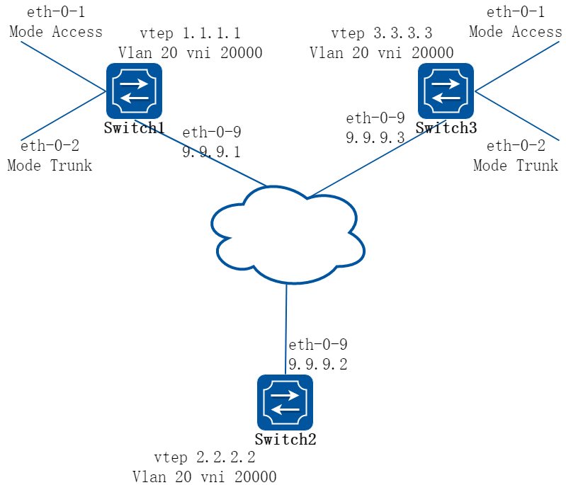
图17-24OVERLAY without Horizon Split
2.配置步骤
在下面的配置举例中,拓扑如上图,switch1和switch2之间建立tunnel,switch2和switch3之间建立tunnel。在switch2上关闭overlay水平分割,使一侧tunnel过来的流量从另一侧tunnel出去。
配置以VXLAN 为例,NVGRE和GENEVE配置是类似的。
以下配置如未说明在哪个Switch配置,则表示所有Switch配置相同:
步骤 1进入配置模式
Switch# configure terminal
步骤 2进入vlan配置模式并创建vlan,在vlan上使能overlay
Switch(config)# vlan database
Switch(config-vlan)# vlan 20
Switch(config-vlan)# vlan 20 overlay enable
Switch(config-vlan)# exit
步骤 3进入接口配置模式,配置接口属性
Switch1 的接口配置:
Switch1(config)# interface eth-0-1
Switch1(config-if)# switchport access vlan 20
Switch1(config-if)# no shutdown
Switch1(config-if)# exit
Switch1(config)# interface eth-0-2
Switch1(config-if)# switchport mode trunk
Switch1(config-if)# switchport trunk allowed vlan add 20
Switch1(config-if)# no shutdown
Switch1(config-if)# exit
Switch1(config)# interface eth-0-9
Switch1(config-if)# no switchport
Switch1(config-if)# ip address 9.9.9.1/24
Switch1(config-if)# overlay uplink enable
Switch1(config-if)# no shutdown
Switch1(config-if)# exit
Switch1(config)# interface loopback0
Switch1(config-if)# ip address 1.1.1.1/32
Switch1(config-if)# exit
Switch2 的接口配置:
Switch2(config-if)# interface eth-0-9
Switch2(config-if)# no switchport
Switch2(config-if)# ip address 9.9.9.2/24
Switch2(config-if)# overlay uplink enable
Switch2(config-if)# no shutdown
Switch2(config-if)# exit
Switch2(config)# interface loopback0
Switch2(config-if)# ip address 2.2.2.2/32
Switch2(config-if)# exit
Switch3 的接口配置:
Switch3(config)# interface eth-0-1
Switch3(config-if)# switchport access vlan 20
Switch3(config-if)# no shutdown
Switch3(config-if)# exit
Switch3(config)# interface eth-0-2
Switch3(config-if)# switchport mode trunk
Switch3(config-if)# switchport trunk allowed vlan add 20
Switch3(config-if)# no shutdown
Switch3(config-if)# exit
Switch3(config)# interface eth-0-9
Switch3(config-if)# no switchport
Switch3(config-if)# ip address 9.9.9.3/24
Switch3(config-if)# overlay uplink enable
Switch3(config-if)# no shutdown
Switch3(config-if)# exit
Switch3(config)# interface loopback0
Switch3(config-if)# ip address 3.3.3.3/32
Switch3(config-if)# exit
步骤 4配置静态路由
在switch1配置:
Switch1(config)# ip route 2.2.2.0/24 9.9.9.2
在switch2配置:
Switch2(config)# ip route 1.1.1.0/24 9.9.9.1
Switch2(config)# ip route 3.3.3.3/24 9.9.9.3
在switch3配置:
Switch3(config)# ip route 2.2.2.0/24 9.9.9.2
步骤 5配置overlay
在switch1配置:
Switch1(config)# overlay
Switch1(config-overlay)# source 1.1.1.1
Switch1(config-overlay)# remote-vtep 1 ip-address 2.2.2.2 type vxlan
Switch1(config-overlay)# vlan 20 vni 20000
Switch1(config-overlay)# vlan 20 remote-vtep 1
Switch1(config-overlay)# exit
在switch2配置:
Switch2(config)# overlay
Switch2(config-overlay)# source 2.2.2.2
Switch2(config-overlay)# remote-vtep 1 ip-address 1.1.1.1 type vxlan split-horizon-disable
Switch2(config-overlay)# remote-vtep 2 ip-address 3.3.3.3 type vxlan split-horizon-disable
Switch2(config-overlay)# vlan 20 vni 20000
Switch2(config-overlay)# vlan 20 remote-vtep 1
Switch2(config-overlay)# vlan 20 remote-vtep 2
Switch2(config-overlay)# exit
在switch3配置:
Switch3(config)# overlay
Switch3(config-overlay)# source 3.3.3.3
Switch3(config-overlay)# remote-vtep 1 ip-address 2.2.2.2 type vxlan
Switch3(config-overlay)# vlan 20 vni 20000
Switch3(config-overlay)# vlan 20 remote-vtep 1
Switch3(config-overlay)# exit
步骤 6退出配置模式
Switch(config)# end
步骤 7检查配置
Switch2 显示结果:
switch2# show overlay remote-vtep
Index Type Virtual-Mac IP-Address Source-Ip Split-Horizon Keep-vtag Dscp-strategy
-------------------------------------------------------------------------------------------
1 VxLAN - 1.1.1.1 2.2.2.2 Disable Disable Dscp-copy
2 VxLAN - 3.3.3.3 2.2.2.2 Disable Disable Dscp-copy
17.5.1概述
简介
OVSDB(Open vSwitch Database, 开放虚拟交换机数据库)是交换机中保存配置信息的数据库。OVSDB数据库主要由两个部分构成,即OVSDB服务器和OVSDB客户端。控制器作为OVSDB客户端,通过OVSDB管理协议,可以对交换机上的OVSDB数据库进行配置和查询,从而实现对网络中的VTEP设备的管理和部署。
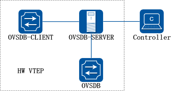
图17-25OVSDB
作为VTEP的交换机设备,在使能OVSDB功能后,会创建并维护OVSDB数据库。当控制器和VTEP设备上的OVSDB服务器连接后,会通过OVSDB管理协议,操作OVSDB数据库中的数据。VTEP设备会将OVSDB数据库中的数据转化为VXLAN的相关配置进行下发。
当前支持的表项如下:
|
表名 |
描述 |
信息来源 |
命令 |
备注 |
|
Global table |
顶层配置,包含当前数据库中管理的物理交换机 |
交换机 |
|
|
|
Manager table |
控制器和OVSDB服务器之间的连接配置 |
交换机或控制器 |
ovsdb controller |
|
|
Physical switch table |
实现硬件VTEP的物理交换机信息 |
交换机 |
|
|
|
Physical port table |
OVSDB管理的接口信息 |
交换机 |
ovsdb port enable |
|
|
Logical switch table |
包含逻辑交换机信息,VXLAN配置可以由这些信息转换而来 |
控制器 |
|
|
|
Physical locator table |
包含网络中的硬件VTEP信息. |
控制器 |
|
|
|
Physical locator set table |
包含硬件VTEP的集合信息 |
控制器 |
|
|
|
Unicast MACs remote table |
包含网络中的单播MAC表项,由控制器下发 |
控制器 |
|
|
|
Multicast MACs remote table |
包含网络中的组播和洪泛表项,由控制器下发 |
控制器 |
|
仅支持unknown dst |
17.5.2配置举例
1.组网拓扑
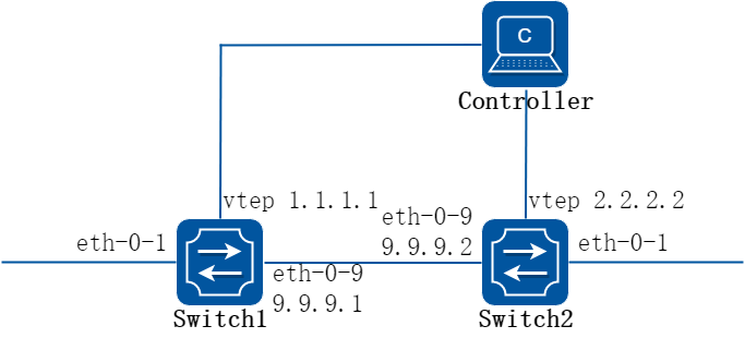
图17-26OVSDB
2.配置步骤
以下配置如未说明在哪个Switch配置,则表示所有Switch配置相同:
步骤 1进入配置模式
Switch# configure terminal
步骤 2进入接口配置模式,配置接口属性
Switch1 的接口配置:
Switch1(config)# interface eth-0-1
Switch1(config-if)# ovsdb port enable
Switch1(config-if)# no shutdown
Switch1(config-if)# exit
Switch1(config)# interface eth-0-9
Switch1(config-if)# no switchport
Switch1(config-if)# ip address 9.9.9.1/24
Switch1(config-if)# overlay uplink enable
Switch1(config-if)# no shutdown
Switch1(config-if)# exit
Switch1(config)# interface loopback0
Switch1(config-if)# ip address 1.1.1.1/32
Switch1(config-if)# exit
Switch2 的接口配置:
Switch2(config)# interface eth-0-1
Switch2(config-if)# ovsdb port enable
Switch2(config-if)# no shutdown
Switch2(config-if)# exit
Switch2(config)# interface eth-0-9
Switch2(config-if)# no switchport
Switch2(config-if)# ip address 9.9.9.2/24
Switch2(config-if)# overlay uplink enable
Switch2(config-if)# no shutdown
Switch2(config-if)# exit
Switch2(config)# interface loopback0
Switch2(config-if)# ip address 2.2.2.2/32
Switch2(config-if)# exit
步骤 3配置静态路由
在switch1配置:
Switch1(config)# ip route 2.2.2.0/24 9.9.9.2
在switch2配置:
Switch2(config)# ip route 1.1.1.0/24 9.9.9.1
步骤 4配置overlay
在switch1配置:
Switch1(config)# overlay
Switch1(config-overlay)# source 1.1.1.1
Switch1(config-overlay)# exit
在switch2配置:
Switch2(config)# overlay
Switch2(config-overlay)# source 2.2.2.2
Switch2(config-overlay)# exit
步骤 5全局使能ovsdb
Switch(config)# ovsdb enable
步骤 6退出配置模式
Switch(config)# end
步骤 7检查配置
Switch1 显示结果:
Switch1# show running
overlay
source 1.1.1.1
!
interface eth-0-1
ovsdb port enable
interface eth-0-9
no switchport
overlay uplink enable
ip address 9.9.9.1/24
interface loopback0
ip address 1.1.1.1/32
!
ovsdb enable
Switch# show ovsdb physical-switch
Physical Switch Name : switch
Management IP address :
Tunnel IP address : 1.1.1.1
17.6.1概述
简介
1.缩略语说明
|
缩略语 |
英文全称 |
翻译与解释 |
|
EVPN |
Ethernet Virtual Private Network |
以太网虚拟专用网络 |
|
VXLAN |
Virtual eXtensible Local Area Network |
虚拟扩展局域网 |
|
IRB |
Integrated Routing and Bridging |
集成式桥接和路由 |
|
RR |
Route Reflector |
路由反射器 |
|
VTEP |
VXLAN Tunnel End Point |
虚拟隧道端点 |
|
VM |
Virtual Machine |
虚拟机 |
|
BUM |
Broadcast, Unknown unicast, or Multicast |
广播,未知单播和组播 |
|
L2 VNI |
Layer 2 Virtual Network Identifier |
二层虚拟网络标识符 |
|
L3 VNI |
Layer 3 Virtual Network Identifier |
三层虚拟网络标识符 |
|
PMSI |
Provider Multicast Service Interface |
运营商组播业务接口 |
|
NLRI |
Network Layer Reachability Information |
网络层可达信息 |
|
BGP |
Border Gateway Protocol |
边界网关协议 |
|
ARP |
Address Resolution Protocol |
地址解析协议 |
|
MLAG |
Multi-Chassis Link Aggregation Group |
跨设备链路聚合 |
2.功能说明
EVPN(Ethernet Virtual Private Network)是一种用于网络互联的VPN技术。EVPN技术采用类似于BGP/MPLS IP VPN的机制,在BGP协议的基础上定义了一种新的NLRI(Network Layer Reachability Information,网络层可达信息)即EVPN NLRI,EVPN NLRI定义了几种新的BGP EVPN路由类型,用于处在二层网络的不同站点之间的MAC地址学习和发布。同时为同一租户的不同子网提供三层互联,并为其提供与外部网络的三层互联。
原有的VXLAN实现方案没有控制平面,是通过数据平面的流量泛洪进行VTEP发现和主机信息(包括IP地址、MAC地址、VNI、网关VTEP IP地址)学习的,这种方式导致网络存在很多泛洪流量。为了解决这一问题,VXLAN引入了EVPN作为控制平面,通过在VTEP之间交换BGP EVPN路由实现VTEP的自动发现、主机信息相互通告等特性,从而避免了不必要的数据流量泛洪。
综上所述,EVPN通过扩展BGP协议新定义了几种BGP EVPN路由,这些BGP EVPN路由可以用于传递VTEP地址和主机信息,因此EVPN应用于VXLAN网络中,可以使VTEP发现和主机信息学习从数据平面转移到控制平面。
在EVPN网络中,有一些常用的基本概念如下:
• 对称路由:当属于同一租户位于不同VTEP的不同子网设备进行三层通信时,在本地VTEP上查询路由加封装转发,到达远端VTEP解封装后再次查询路由转发,此时称为对称路由,在对称路由模式下往返通常使用相同的VNI。
• 非对称路由:当属于同一租户位于不同VTEP的不同子网设备进行三层通信时,在本地VTEP上查询路由加封装转发,到达远端VTEP解封装后查询二层转发表项转发,此时称为非对称路由,在非对称式路由模式下往返通常使用不同的VNI。
• L2VNI:二层VNI,以1:1的方式和VLAN进行映射,处于同一个大二层内的设备有相同的L2VNI,互相通信经过使用该VNI。在非对称路由模式下属于同一租户但不同子网的设备进行通信,那将使用目的设备所属L2VNI进行加封装。
• L3VNI:三层VNI,以1:1的方式和VRF进行映射,对称路由模式下属于同一租户但不同子网的设备进行通信时统一使用该VNI。
• EVPN实例:一个二层VNI对应一个EVPN实例,每个EVPN实例有独立的RD,Route-Target属性
背景
VXLAN是应用于数据中心虚拟化的一种NVO3(Network Virtualization over Layer 3 )技术,主要解决多租户接入扩展和VM迁移等场景应用。 现有VXLAN没有控制面,都是通过基于多播的洪泛方式,通过数据平面进行VTEP发现和远端主机地址学习,导致数据中心网络中存在很多泛洪流量。
为了克服通过洪泛方式进行学习,IETF标准草案(draft-ietf-bess-evpn-overlay-02.txt) 定义了MP-BGP EVPN作为VXLAN控制平面。 EVPN 作为控制面,能提供VXLAN隧道自动发现、主机信息(主机IP、主机MAC、主机 ARP)控制面通告等特性。正因为主机信息通过 EVPN 控制面的通告,避免了流量泛洪。
原理描述
1.报文格式
![]() VXLAN 报文格式说明参考 《VXLAN》相关章节。
VXLAN 报文格式说明参考 《VXLAN》相关章节。
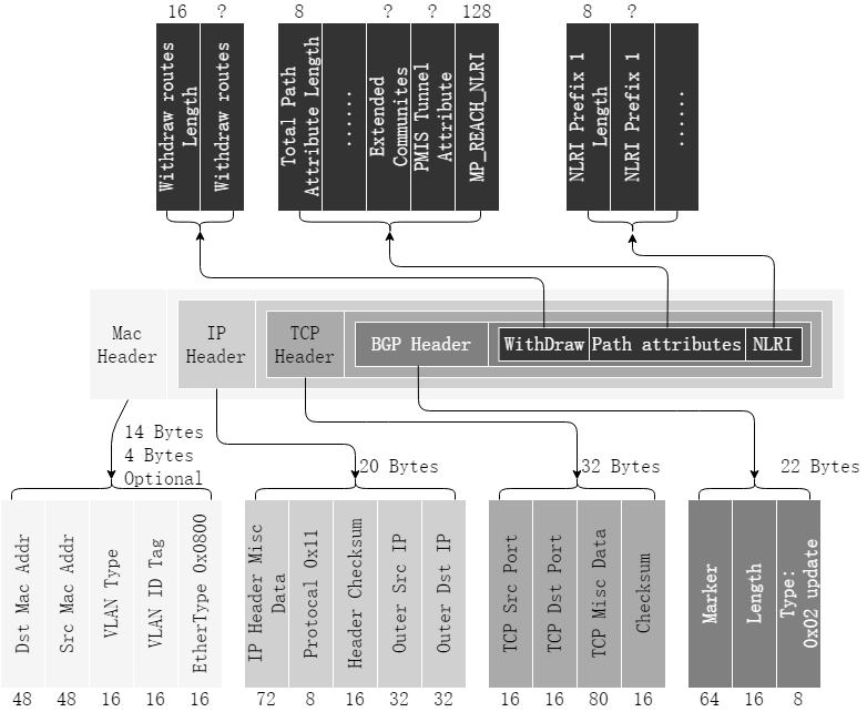
图17-27BGP Update报文格式
EVPN的协议报文封装在BGP报文的Path attribute中,以NLRI的形式来携带。 下面会详细介绍EVPN NLRI中定义的路由类型及其报文格式以及作用。
Withdraw路由
![]()
图17-28Withdraw路由报文格式
Withdraw 路由包含要撤销的路由列表,列表中的每个单元包含8 Bytes的Length域和可变长度的Prefix域。
表17-1Withdraw路由报文字段解释
|
字段 |
解释说明 |
|
Withdraw routes length |
待撤销路由的长度。其值为零时,表示没有撤销的路由 |
|
Withdraw routes |
需要撤销的路由prefix |
BGP EXTEMDED_COMMUNITIES
BGP的EXTEMDED_COMMUNITIES是BGP报文中Path Attribute的一类,用于携带BGP的扩展团体属性。其中,EVPN的Route target信息会通过这个属性来携带。
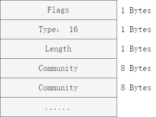
图17-29EXTEMDED_COMMUNITIES 报文格式
通过Community Transitive Two-Octet AS Route target类型团体属性携带AS和AN(即Route Target)。
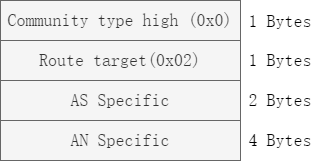
图17-30Community Transitive Two-Octet AS Route target 报文格式
Community Transitive Opaque Encapsulation属性指定了封装类型。
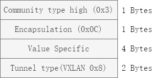
图17-31Community Transitive Opaque Encapsulation 报文格式
为了在VTEP间相互通告VTEP IP,VNI,下联主机地址等信息,在EVPN NLRI中定义了如下几种应用于VXLAN控制平面的BGP EVPN路由类型:
• Type2路由(MAC/IP路由)
• Type3路由(Inclusive Multicast路由)
• Type5路由(IP前缀路由)
下面分别介绍这三种类型的路由:
Type2路由(MAC/IP路由)
Type2路由用于将本VTEP下挂的主机MAC/IP通告给远端VTEP,该类型路由报文格式如下图所示。
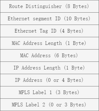
图17-32Type2路由报文格式
表17-2Type2路由报文字段解释
|
字段 |
解释说明 |
|
Route Distinguisher |
该字段为EVPN实例下设置的RD(Route Distinguisher)值。 |
|
Ethernet Segment Identifier |
该字段为当前设备与对端连接定义的唯一标识。(目前为全0) |
|
Ethernet Tag ID |
该字段为当前设备上实际配置的VLAN ID。(目前为全0) |
|
MAC Address Length |
该字段为此路由携带的主机MAC地址的长度。 |
|
MAC Address |
该字段为此路由携带的主机MAC地址。 |
|
IP Address Length |
该字段为此路由携带的主机IP地址的掩码长度。 |
|
IP Address |
该字段为此路由携带的主机IP地址。 |
|
MPLS Label1 |
该字段为此路由携带的二层VNI。 |
|
MPLS Label2 |
该字段为此路由携带的三层VNI。 |
该类型主要作用包括,以对称式路由为例:
• 主机MAC通告: 要实现同子网主机的二层互访,两端VTEP需要相互学习主机MAC。作为BGP EVPN邻居的VTEP之间通过交换Type2路由,可以相互通告已经获取到的主机MAC。其中,MAC Address Length和MAC Address字段为主机MAC地址。当仅需通告MAC时,Type2路由中不需要携带三层VNI和IP Address,同时IP Address Length填为0。
• 主机IP通告: 在分布式网关场景中,要实现跨子网主机的三层互访,两端VTEP(作为三层网关)需要互相学习主机IP路由。作为BGP EVPN邻居的VTEP之间通过交换Type2路由,可以相互通告已经获取到的主机IP路由。其中,IP Address Length和IP Address字段为主机IP路由的目的地址,同时MPLS Label2字段必须携带三层VNI。此时的MAC/IP路由也称为IRB(Integrated Routing and Bridge)类型路由。
Type3路由(Inclusive Multicast路由)
Type3路由由前缀和PMSI属性组成,VTEP IP地址存放在前缀的Originating Router’s IP Address字段中,VNI存放在PMSI属性的MPLS Label字段中。该类型路由在VXLAN控制平面中主要用于VTEP的自动发现和VXLAN隧道的动态建立。作为BGP EVPN邻居的VTEP,通过Inclusive Multicast路由互相传递二层VNI和VTEP IP地址信息。当收到的报文中携带了与本地配置相同的VNI就会创建一个头端复制表,用于后续BUM报文转发。该类型路由报文格式如下图所示。
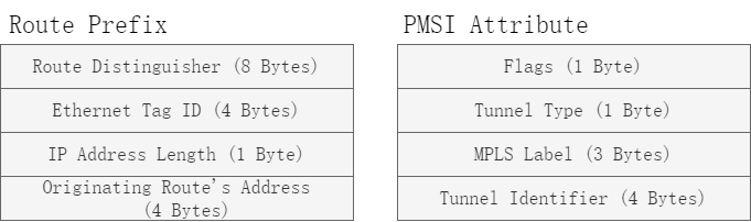
图17-33Type3路由前缀和PMSI属性
表17-3Type3路由前缀和PMSI属性字段解释
|
字段 |
解释说明 |
|
Route Distinguisher |
该字段为EVPN实例下设置的RD(Route Distinguisher)值。 |
|
Ethernet Tag ID |
该字段为当前设备上实际配置的VLAN ID。(目前为全0) |
|
IP Address Length |
该字段为此路由携带的本端VTEP IP地址的掩码长度。 |
|
Originating Router’s IP Address |
该字段为此路由携带的本端VTEP IP地址。 |
|
Flags |
该字段为标志位,标识当前隧道是否需要叶子节点信息。 在VXLAN场景中,该字段没有实际意义。 |
|
Tunnel Type |
该字段为此路由携带的隧道类型。目前,在VXLAN场景中,支持的类型只有“6:Ingress Replication”,即头端复制,用于BUM报文转发。 |
|
MPLS Label |
该字段为此路由携带的二层VNI。 |
|
Tunnel Identifier |
该字段为此路由携带的隧道信息。目前,在VXLAN场景中,该字段也是本端VTEP IP地址。 |
Type5路由(IP前缀路由)
该类型路由用来通告网段地址实现VXLAN网络中的主机访问外部网络。该类型路由报文格式如下图所示。
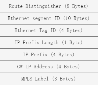
图17-34Type5路由报文格式
表17-4Type5路由报文字段解释
|
字段 |
解释说明 |
|
Route Distinguisher |
该字段为EVPN实例下设置的RD(Route Distinguisher)值。 |
|
Ethernet Segment Identifier |
该字段为当前设备与对端连接定义的唯一标识。(目前为全0) |
|
Ethernet Tag ID |
该字段为当前设备上实际配置的VLAN ID。(目前为全0) |
|
IP Prefix Length |
该字段为此路由携带的IP前缀掩码长度,一般不为32。 |
|
IP Prefix |
该字段为此路由携带的IP前缀。 |
|
GW IP Address |
该字段为默认网关地址。该字段在VXLAN场景中没有实际意义。 |
|
MPLS Label |
该字段为此路由携带的三层VNI。 |
2.二层VXLAN隧道建立
不使用EVPN的情况下,VXLAN网络中隧道是通过手动配置VNI到VNI对应的peer列表创建VXLAN隧道,这种方案配置量大,非常不方便。
引入EVPN作为控制平面后,可利用EVPN中的inclusive路由(Type3)来传递L2 VNI和VTEP地址信息,从而实现动态创建L2 VXLAN 隧道,减少大量的配置,提高部署效率。
EVPN使用Type3路由,即Inclusive multicast路由,通过该路由传递本地L2 VNI + L2 VTEP信息,实现VXLAN隧道自动发现。

图17-35Type 3路由在VXLAN 隧道自动发现时的应用
VXLAN隧道由一对VTEP IP地址确定,创建VXLAN隧道实际上是两端VTEP获取对端VTEP IP地址的过程,只要对端VTEP IP地址是三层路由可达的,VXLAN隧道就可以建立成功。通过BGP EVPN方式动态建立VXLAN隧道,就是在两端VTEP之间建立BGP EVPN邻居,然后邻居之间利用BGP EVPN Type3路由来互相传递VNI和VTEP IP地址信息,从而实现动态建立VXLAN隧道。
如下图所示,Vtep-1,Vtep-2上分别部署了一个Host,其属于同一网段只需要在Vtep-1和Vtep-2之间创建一条的VXLAN隧道用于二层转发;
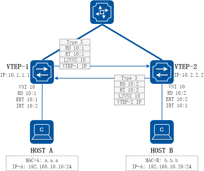
图17-36VXLAN隧道示意
首先在Vtep-1和Vtep-2之间建立BGP EVPN邻居。然后创建EVPN实例,配置本端EVPN实例的RD、出方向Route-Target(ERT)、入方向Route-Target(IRT)。在配置完本端VTEP IP地址后,Vtep-1和Vtep-2会生成BGP EVPN Type3路由并发送给对端,该路由携带本端EVPN实例的出方向Route-Target,Leaf1和Leaf2在收到对端发来的BGP EVPN Type3路由后,首先检查该路由中携带的Route-Target如果与本端EVPN实例的入方向Route-Target相等,则接收该路由,否则丢弃该路由。在接收该路由后,Leaf1和Leaf2将获取其中携带的对端VTEP IP地址和VNI,如果对端VNI与本端相同,则创建一个到对端VTEP IP的VXLAN隧道,用于后续BUM报文转发。
3.MAC表项同步
同网段主机互访时,互相学习到对方主机MAC后,可以通过二层已知单播转发。 在没有引入EVPN控制面时,VXLAN网络的主机是依赖数据流量泛洪来学习主机MAC的。 通过EVPN的Type2路由传递主机MAC,可以减少VXLAN网络的流量泛洪。
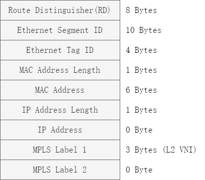
图17-37Type 2 路由在主机MAC通告时的应用
同上一小节图示,HOST A与HOST B属于同一网段,完成隧道建立后由于没有具体的MAC转发表项,相互之间的流量会通过广播的方式进行转发,造成不必要的带宽浪费,当MAC完成同步后则会大大减小带宽浪费。
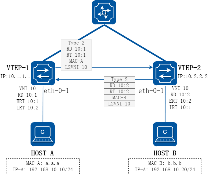
图17-38MAC表项同步示意
HostA首次与VTEP-1通信时, VTEP-1学习到HostA的MAC地址、所属VLAN和报文入接口(eth-0-1)的对应关系,并在本地MAC表中生成HostA的MAC表项,其出接口为eth-0-1。同时VTEP-1根据HostA的MAC表项生成BGP EVPN路由并发送给VTEP-2,该路由携带本端EVPN实例的出方向Route-Target、路由下一跳属性以及BGP EVPN协议定义的Type2路由即MAC/IP路由。其中,路由下一跳属性携带的是本端VTEP IP地址;HostA的MAC地址存放在MAC Address Length和MAC Address字段中,二层VNI(将学习到的MAC对应的vlan映射到的相应VNI)存放在MPLS Label1字段中。由于此时只是二层通信只需同步MAC即可,所以Type2路由中不需要携带主机IP及三层VNI的信息。
VTEP-2收到VTEP-1发来的BGP EVPN路由后,首先检查该路由携带的Route-Target,如果与本端EVPN实例的入方向Route-Target相等,则继续比较L2VNI是否与该EVPN实例配置的L2VNI相同,如相同则接收该路由,否则丢弃该路由。在接收该路由后,VTEP-2获得HostA的MAC地址、L2VNI和VTEP-1上VTEP IP地址(下一跳属性)的对应关系,并在本地的MAC表中生成HOSTA的MAC表项,其出接口为指向VTEP-1的VXLAN隧道,对应VNI为相应二层VNI。
4.主机路由同步
Type2 路由可以同时携带主机MAC+主机IP,因而可以用来传递主机ARP。当学到主机的 ARP 后,就可以通过上面路由去向邻居发送主机 ARP;远端邻居收到 ARP 后,将ARP表项保存到本地的ARP缓存列表中。
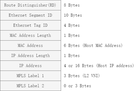
图17-39Type 2 路由在主机ARP通告时的应用
当VTEP下联的主机属于不同网段时但是需要互相通信时需要借助三层转发来完成,那么此时仅进行MAC同步则无法完成通信,需要通过Type2消息将主机的IP地址和下一跳的相应信息也通告给对端才能保证相互之间能通过路由互通。
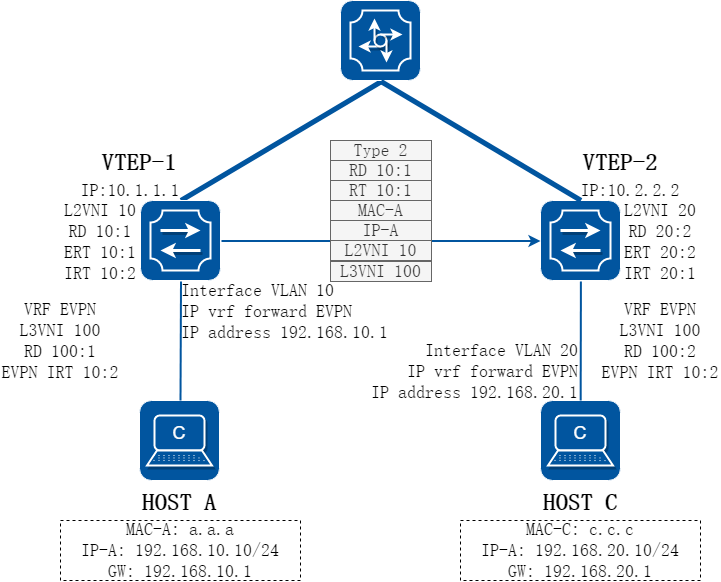
图17-40主机路由同步示意
如上图所示,HostA和HostC属于不同的网段,需要相互通告路由才能完成通信,通过请求网关物理地址的ARP报文,VTEP-1可以学习到HostA的ARP表项,获得HostA的MAC和IP信息。VTEP-1由HostA的MAC所在vlan得到相应的L2VNI,同时学到该ARP的三层接口(inteface vlan 10)绑定了vrf实例(vrf EVPN),vrf实例又关联了三层VNI,VTEP-1可以得到HostA所属的三层VNI,有了MAC/IP/二层VNI/三层VNI信息后,VTEP-1上的EVPN实例就可以根据上述信息生成Type2(IRB)路由,其中主机MAC信息和二层VNI信息同2.3 节所示,主机IP地址存放在IP Address Length和IP Address字段中,三层VNI存放在MPLS Label2字段中,RD和Route-Target为EVPN实例的RD和出方向Route-Target。
VTEP-2收到VTEP-1发来的Type2路由后,检查该路由携带的Route-Target是否与本端VRF实例(本例VRF名字为EVPN,并非强制,VRF名字可以为其他字符串)的入方向EVPN Route-Target相等,若相等,则接收该路由,否则丢弃该路由。在接收该路由后,VTEP-2获得HostA的MAC地址、IP地址、L2VNI、L3VNI和VTEP-1上VTEP IP地址(下一跳属性)的对应关系,并在本地的vrf路由表中生成到HostA的32位路由,其出接口为指向VTEP-1的VXLAN隧道,VNI为相应的三层VNI。
5.网段路由同步
EVPN网络构建的是一个私有网络,它也可以通过接入外网,实现跟外网通信的目的。BGP通过Type5 IP前缀路由来完成外部路由的导入。 通常在EVPN的Spine-Leaf架构中,会有1台或多台专门接入外网的设备,我们把它叫做Border Leaf。Border Leaf通过普通接口从外网学习路由,并将这些路由引入EVPN地址族,形成EVPN 5类路由,进而通告到EVPN网络中,使其他VTEP也能学到这些外部路由。
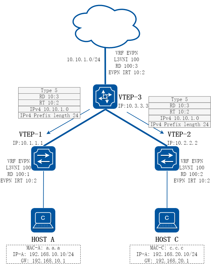
图17-41Type 5 路由在主机IP通告时的应用
在上一节中,通过Type2路由解决了32位的主机路由的同步问题,但是当需要与外部网络通信时,仅能同步32位的主机路由显然无法满足通信要求,因此EVPN通过Type5路由来解决网段路由同步。
图17-42网段路由同步示意
如上图所示,VTEP-3上的vrf EVPN内有一条外部路由,需要将其通告给VTEP-1/VTEP-2后HostA/HostC才能访问该网段内地址。VTEP-3将该路由所在vrf的三层VNI,VTEP-3的IP地址,RD,以及EVPN Export Route-Target信息封装在type5路由中发送给远端VTEP,在EVPN邻居收到该消息后,首先判断报文中携带的Route-Target是否与本地vrf配置Import Route-Target相同,相同则接收该路由,取出IPv4地址及掩码长度来组成路由前缀,其出接口为指向VTEP-3的VXLAN隧道,VNI为相应的三层VNI。
17.6.2应用场景
路由反射器在BGP EVPN组网中的应用
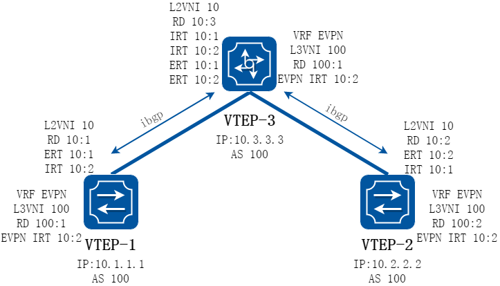
图17-43路由反射器示意
如上图所示实例中,VTEP-1/VTEP-2都与VTEP-3建立ibgp的evpn邻居,默认情况下从ibgp收到的路由不会再向其他ibgp邻居发送,此时VTEP-1和VTEP-2之间就无法收到对面的路由。 为了在此种情况下VTEP-1和VTEP-2之间也能互相学习到路由,可以在VTEP-3的bgp evpn地址族下配置neighbor 10.1.1.1 route-reflector-client、neighbor 10.2.2.2 route-reflector-client,使能路由反射器功能,配置完成后,VTEP-3就会将从ibgp发布过来的路由反射到另外的ibgp,此时VTEP-1和VTEP-2就能互相学习到路由了。
Retain route target
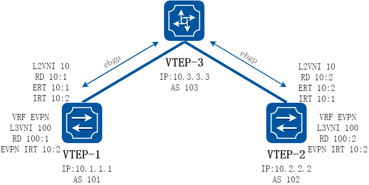
图17-44Retain route target示意
如上图所示实例中,VTEP-1/VTEP-2都与VTEP-3建立ebgp的evpn邻居,VTEP-1和VTEP-2上都存在EVPN实例,而VTEP-3上目前暂未部署EVPN实例,此时VTEP-3收到VTEP-1和VTEP-2发布给自己的路由后,由于没有EVPN实例会将这些路由丢弃,导致VTEP-1和VTEP-2也不能相互学习对面的EVPN路由。 为了在此种情况下VTEP-1和VTEP-2之间也能互相学习到路由,可以在VTEP-3的bgp evpn地址族下配置retain route-target all,配置完成后,VTEP-3会暂存收到的所有bgp evpn路由并发布给自己的邻居,这样VTEP-1和VTEP-2之间就能互相学习到路由了。
allowas-in
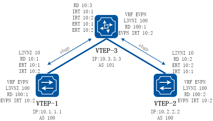
图17-45allowas-in示意
如上图所示实例中,VTEP-1/VTEP-2都与VTEP-3建立ebgp的evpn邻居,VTEP-1要将路由发布给VTEP-2时需要经过VTEP-3,此时VTEP-2收到的BGP EVPN路由中,AS PATH将包含VTEP-1本地的AS号(100),由于VTEP-1和VTEP-2的AS相同,默认情况下BGP不接收AS PATH中包含本地AS的路由通告 为了在此种情况下VTEP-1和VTEP-2之间也能互相学习到路由,可以在VTEP-2上的evpn地址族下配置neighbor 10.3.3.3 allowas-in,配置完成后BGP就会接收AS PATH中包含本地AS的路由通告。
attribute-unchanged

图17-46attribute-unchanged示意
如上图所示实例中,VTEP-1/VTEP-2都与VTEP-3建立ebgp的evpn邻居,VTEP-1要将路由发布给VTEP-2需要经过VTEP-3,默认情况下在VTEP-3将从VTEP-1过来的路由发送给VTEP-2时,会将路由中的nexthop等信息替换为VTEP-3本地的地址,此时VTEP-2上建立的隧道将是到VTEP-3的。 如果想在VTEP-1和VTEP-2之间之间建立隧道,可以在VTEP-3的bgp evpn地址族下配置neighbor 10.1.1.1 attribute-unchanged、neighbor 10.2.2.2 attribute-unchanged,此时从VTEP-3发布出去的路由将不会更改nexthop等信息。
evpn virtual-mac enable
当需要双活接入VXLAN网络时,我们推荐采用MLAG的方式进行接入,此时MLAG的两台设备需要对外表现为同一个VTEP,即对外采用相同的VTEP IP/MAC,VTEP IP在NVE接口上配置,配置evpn virtual-mac enable后,VTEP MAC借用VARP配置虚拟MAC,MLAG两侧设备的虚拟MAC需要配置相同。
17.6.3配置举例
BGP EVPN方式部署集中式网关
1.组网拓扑
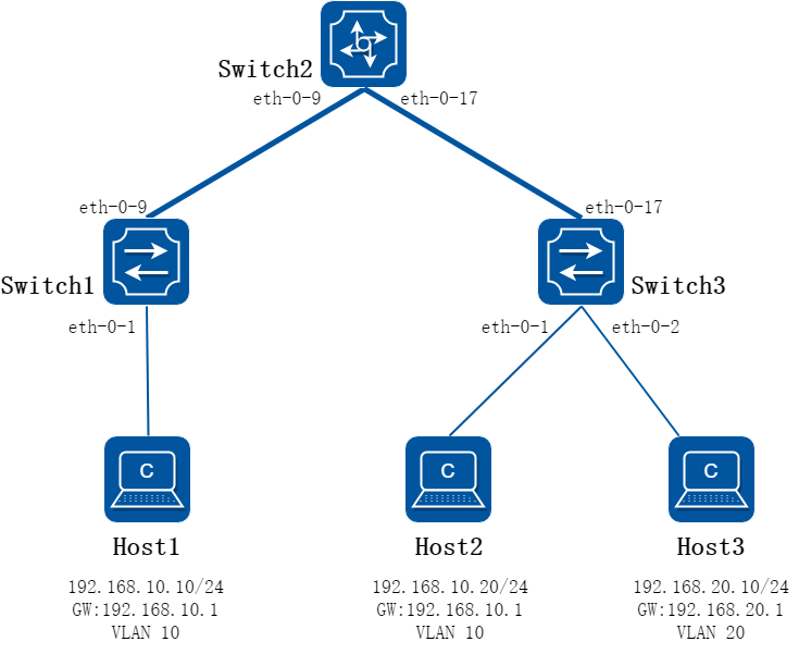
图17-47BGP EVPN方式部署集中式网关
2.组网需求
Host 1和Host 2处于同一网段,Host3处于另一个网段,其底层网络为三层网络,需要通过VXLAN隧道来实现互通
3.配置思路
Switch 1和Switch 3分别与Switch 2建立IBGP邻居,同时Switch 2上使能路由反射器,使得Switch 1和Switch 3能互相学习到BGP EVPN路由,Host 1能与Host 2互通。 同时在Switch 2上部署集中式网关,需要跨子网互通的流量经Switch 2路由转发
4.配置步骤
步骤 1配置路由,保证交换机之间三层网络可通
配置Switch 1
Switch1# configure terminal
Enter configuration commands, one per line. End with CNTL/Z.
Switch1(config)# interface loopback 0
Switch1(config-if)# ip address 10.1.1.1/32
Switch1(config-if)# exit
Switch1(config)# interface eth-0-9
Switch1(config-if)# no switchport
Switch1(config-if)# ip address 192.168.1.1/24
Switch1(config-if)# vxlan uplink enable
Switch1(config-if)# no shutdown
Switch1(config-if)# exit
Switch1(config)# ip route 10.2.2.2/32 192.168.1.2
Switch1(config)# ip route 10.3.3.3/32 192.168.1.2
Switch1(config)# end
配置Switch 2
Switch2# configure terminal
Enter configuration commands, one per line. End with CNTL/Z.
Switch2(config)# interface loopback 0
Switch2(config-if)# ip address 10.2.2.2/32
Switch2(config-if)# exit
Switch2(config)# interface eth-0-9
Switch2(config-if)# no switchport
Switch2(config-if)# ip address 192.168.1.2/24
Switch2(config-if)# vxlan uplink enable
Switch2(config-if)# no shutdown
Switch2(config-if)# exit
Switch2(config)# interface eth-0-17
Switch2(config-if)# no switchport
Switch2(config-if)# ip address 192.168.2.1/24
Switch2(config-if)# vxlan uplink enable
Switch2(config-if)# no shutdown
Switch2(config-if)# exit
Switch2(config)# ip route 10.1.1.1/32 192.168.1.1
Switch2(config)# ip route 10.3.3.3/32 192.168.2.2
Switch2(config)# end
配置Switch 3
Switch3# configure terminal
Enter configuration commands, one per line. End with CNTL/Z.
Switch3(config)# interface loopback 0
Switch3(config-if)# ip address 10.3.3.3/32
Switch3(config-if)# exit
Switch3(config)# interface eth-0-17
Switch3(config-if)# no switchport
Switch3(config-if)# ip address 192.168.2.2/24
Switch3(config-if)# vxlan uplink enable
Switch3(config-if)# no shutdown
Switch3(config-if)# exit
Switch3(config)# ip route 10.1.1.1/32 192.168.2.1
Switch3(config)# ip route 10.2.2.2/32 192.168.2.1
Switch3(config)# end
步骤 2配置VLAN
配置Switch 1
Switch1# configure terminal
Enter configuration commands, one per line. End with CNTL/Z.
Switch1(config)# vlan database
Switch1(config-vlan)# vlan 10
Switch1(config-vlan)# vlan 10 overlay enable
Switch1(config-vlan)# exit
Switch1(config)# interface eth-0-1
Switch1(config-if)# switchport mode trunk
Switch1(config-if)# switchport trunk allowed vlan add 10
Switch1(config-if)# no shutdown
Switch1(config-if)# end
配置Switch 2
Switch2# configure terminal
Enter configuration commands, one per line. End with CNTL/Z.
Switch2(config)# vlan database
Switch2(config-vlan)# vlan 10
Switch2(config-vlan)# vlan 10 overlay enable
Switch2(config-vlan)# vlan 20
Switch2(config-vlan)# vlan 20 overlay enable
Switch2(config-vlan)# exit
Switch2(config)# ip vrf evpn
Switch2(config-vrf)# quit
Switch2(config)# interface vlan 10
Switch2(config-if)# ip address 192.168.10.1/24
Switch2(config-if)# interface vlan 20
Switch2(config-if)# ip address 192.168.20.1/24
Switch2(config-if)# end
配置Switch 3
Switch3# configure terminal
Enter configuration commands, one per line. End with CNTL/Z.
Switch3(config)# vlan database
Switch3(config-vlan)# vlan 10
Switch3(config-vlan)# vlan 10 overlay enable
Switch3(config-vlan)# vlan 20
Switch3(config-vlan)# vlan 20 overlay enable
Switch3(config-vlan)# exit
Switch3(config)# interface eth-0-1
Switch3(config-if)# switchport mode trunk
Switch3(config-if)# switchport trunk allowed vlan add 10
Switch3(config-if)# no shutdown
Switch3(config)# interface eth-0-2
Switch3(config-if)# switchport mode trunk
Switch3(config-if)# switchport trunk allowed vlan add 20
Switch3(config-if)# no shutdown
Switch3(config-if)# end
步骤 3配置EVPN实例
配置Switch 1
Switch1# configure terminal
Enter configuration commands, one per line. End with CNTL/Z.
Switch1(config)# overlay
Switch1(config-overlay)# vlan 10 vni 10
Switch1(config-overlay)# quit
Switch1(config)# interface nve 0
Switch1(config-if)# source loopback 0
Switch1(config-if)# member vni 10
Switch1(config-if)# quit
Switch1(config)# evpn
Switch1(config-evpn)# vni 10
Switch1(config-evi)# rd 10:1
Switch1(config-evi)# route-target both 10:10
Switch1(config-evpn)# end
配置Switch 2
Switch2# configure terminal
Enter configuration commands, one per line. End with CNTL/Z.
Switch2(config)# overlay
Switch2(config-overlay)# vlan 10 vni 10
Switch2(config-overlay)# vlan 20 vni 20
Switch2(config-overlay)# quit
Switch2(config)# interface nve 0
Switch2(config-if)# member vni 10
Switch2(config-if)# member vni 20
Switch2(config-if)# source loopback 0
Switch2(config-if)# quit
Switch2(config)# evpn
Switch2(config-evpn)# vni 10
Switch2(config-evi)# rd 10:2
Switch2(config-evi)# route-target both 10:10
Switch2(config-evi)# vni 20
Switch2(config-evi)# rd 20:2
Switch2(config-evi)# route-target both 20:20
Switch2(config-evi)# end
配置Switch 3
Switch3# configure terminal
Enter configuration commands, one per line. End with CNTL/Z.
Switch3(config)# overlay
Switch3(config-overlay)# vlan 10 vni 10
Switch3(config-overlay)# vlan 20 vni 20
Switch3(config-overlay)# exit
Switch3(config)# interface nve 0
Switch3(config-if)# source loopback 0
Switch3(config-if)# member vni 10
Switch3(config-if)# member vni 20
Switch3(config-if)# quit
Switch3(config)# evpn
Switch3(config-evpn)# vni 10
Switch3(config-evi)# rd 10:3
Switch3(config-evi)# route-target both 10:10
Switch3(config-evi)# vni 20
Switch3(config-evi)# rd 20:3
Switch3(config-evi)# route-target both 20:20
Switch3(config-evi)# end
步骤 4配置BGP
配置Switch 1
Switch1# configure terminal
Enter configuration commands, one per line. End with CNTL/Z.
Switch1(config)# router bgp 100
Switch1(config-router)# bgp router-id 10.1.1.1
Switch1(config-router)# neighbor 10.2.2.2 remote-as 100
Switch1(config-router)# neighbor 10.2.2.2 update-source loopback 0
Switch1(config-router)# address-family l2vpn evpn
Switch1(config-router-af)# neighbor 10.2.2.2 activate
Switch1(config-router-af)# neighbor 10.2.2.2 send-community both
Switch1(config-router-af)# end
配置Switch 2
Switch2# configure terminal
Enter configuration commands, one per line. End with CNTL/Z.
Switch2(config)# router bgp 100
Switch2(config-router)# bgp router-id 10.2.2.2
Switch2(config-router)# neighbor 10.1.1.1 remote-as 100
Switch2(config-router)# neighbor 10.1.1.1 update-source loopback 0
Switch2(config-router)# neighbor 10.3.3.3 remote-as 100
Switch2(config-router)# neighbor 10.3.3.3 update-source loopback 0
Switch2(config-router)# address-family l2vpn evpn
Switch2(config-router-af)# neighbor 10.1.1.1 activate
Switch2(config-router-af)# neighbor 10.1.1.1 send-community both
Switch2(config-router-af)# neighbor 10.1.1.1 route-reflector-client
Switch2(config-router-af)# neighbor 10.3.3.3 activate
Switch2(config-router-af)# neighbor 10.3.3.3 send-community both
Switch2(config-router-af)# neighbor 10.3.3.3 route-reflector-client
Switch2(config-router-af)# end
配置Switch 3
Switch3# configure terminal
Enter configuration commands, one per line. End with CNTL/Z.
Switch3(config)# router bgp 100
Switch3(config-router)# bgp router-id 10.3.3.3
Switch3(config-router)# neighbor 10.2.2.2 remote-as 100
Switch3(config-router)# neighbor 10.2.2.2 update-source loopback 0
Switch3(config-router)# address-family l2vpn evpn
Switch3(config-router-af)# neighbor 10.2.2.2 activate
Switch3(config-router-af)# neighbor 10.2.2.2 send-community both
Switch3(config-router-af)# end
步骤 5验证配置结果
检查底层网络是否互通
Switch1# ping -a 10.1.1.1 10.2.2.2
PING 10.2.2.2 (10.2.2.2) from 10.1.1.1 : 56(84) bytes of data.
64 bytes from 10.2.2.2: icmp_seq=1 ttl=64 time=1.98 ms
64 bytes from 10.2.2.2: icmp_seq=2 ttl=64 time=1.91 ms
64 bytes from 10.2.2.2: icmp_seq=3 ttl=64 time=2.02 ms
64 bytes from 10.2.2.2: icmp_seq=4 ttl=64 time=1.93 ms
64 bytes from 10.2.2.2: icmp_seq=5 ttl=64 time=1.94 ms
--- 10.2.2.2 ping statistics ---
5 packets transmitted, 5 received, 0% packet loss, time 4005ms
rtt min/avg/max/mdev = 1.911/1.958/2.022/0.062 ms
Switch1# ping -a 10.1.1.1 10.3.3.3
PING 10.3.3.3 (10.3.3.3) from 10.1.1.1 : 56(84) bytes of data.
64 bytes from 10.3.3.3: icmp_seq=1 ttl=63 time=2.14 ms
64 bytes from 10.3.3.3: icmp_seq=2 ttl=63 time=1.90 ms
64 bytes from 10.3.3.3: icmp_seq=3 ttl=63 time=1.82 ms
64 bytes from 10.3.3.3: icmp_seq=4 ttl=63 time=1.92 ms
64 bytes from 10.3.3.3: icmp_seq=5 ttl=63 time=1.93 ms
--- 10.3.3.3 ping statistics ---
5 packets transmitted, 5 received, 0% packet loss, time 4005ms
rtt min/avg/max/mdev = 1.827/1.946/2.140/0.104 ms
检查隧道建立是否成功
Switch1# show overlay tunnel
-------------------------------------------------------------------------------
Vlan Vni Type Remote-vtep IP-Address Src-Address Head-end-flooding Protocol
10 10 VxLAN - 10.2.2.2 10.1.1.1 Enable Evpn
10 10 VxLAN - 10.3.3.3 10.1.1.1 Enable Evpn
Switch2# show overlay tunnel
-------------------------------------------------------------------------------
Vlan Vni Type Remote-vtep IP-Address Src-Address Head-end-flooding Protocol
10 10 VxLAN - 10.1.1.1 10.2.2.2 Enable Evpn
10 10 VxLAN - 10.3.3.3 10.2.2.2 Enable Evpn
20 20 VxLAN - 10.3.3.3 10.2.2.2 Enable Evpn
Switch3# show overlay tunnel
-------------------------------------------------------------------------------
Vlan Vni Type Remote-vtep IP-Address Src-Address Head-end-flooding Protocol
10 10 VxLAN - 10.1.1.1 10.3.3.3 Enable Evpn
10 10 VxLAN - 10.2.2.2 10.3.3.3 Enable Evpn
20 20 VxLAN - 10.2.2.2 10.3.3.3 Enable Evpn
检查Host间两两是否可以ping通
Host1 ping Host2:
PING 192.168.10.20 from 192.168.10.10: 56 data bytes
64 bytes from 192.168.10.20: icmp_seq=1 ttl=64 time=0.947 ms
--- ping statistics ---
1 packets transmitted, 1 packets received, 0.0% packet loss
rtt min/avg/max/stddev = 0.947/0.947/0.947/0.000 ms
Host1 ping Host3:
PING 192.168.20.10 from 192.168.10.10: 56 data bytes
64 bytes from 192.168.20.10: icmp_seq=1 ttl=63 time=0.613 ms
--- ping statistics ---
1 packets transmitted, 1 packets received, 0.0% packet loss
rtt min/avg/max/stddev = 0.613/0.613/0.613/0.000 ms
Host2 ping Host3:
PING 192.168.20.10 from 192.168.10.20: 56 data bytes
64 bytes from 192.168.20.10: icmp_seq=1 ttl=63 time=1.131 ms
--- ping statistics ---
1 packets transmitted, 1 packets received, 0.0% packet loss
rtt min/avg/max/stddev = 1.131/1.131/1.131/0.000 ms
BGP EVPN方式部署分布式网关
1.组网拓扑
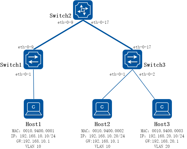
图17-48BGP EVPN方式部署集中式网关
2.组网需求
如上图所示,HOST1、2、3都属于租户test,其间既有相同网段又有不同网段,且都需要相互通信。Switch 1/3之间为三层网络,为了减轻网关压力Switch 1和Switch 3作为下联host的分布式网关,需要通过配置VXLAN在HOST之间建立隧道
3.配置思路
Switch 1和Switch 3分别与Switch 2建立IBGP邻居,同时Switch 2上使能路由反射器,使得Switch 1和Switch 3能互相学习到BGP EVPN路由,配置分布式网关,将host的网关都部署在TOR上,配置使能分布式网关后,vxlan加解封装都在TOR上完成,因此在Switch 2上无需配置evpn实例。
4.配置步骤
步骤 1配置路由,保证交换机之间三层网络可通
配置Switch 1
Switch1# configure terminal
Enter configuration commands, one per line. End with CNTL/Z.
Switch1(config)# interface loopback 0
Switch1(config-if)# ip address 10.1.1.1/32
Switch1(config-if)# exit
Switch1(config)# interface eth-0-9
Switch1(config-if)# no switchport
Switch1(config-if)# ip address 192.168.1.1/24
Switch1(config-if)# vxlan uplink enable
Switch1(config-if)# no shutdown
Switch1(config-if)# exit
Switch1(config)# ip route 10.2.2.2/32 192.168.1.2
Switch1(config)# ip route 10.3.3.3/32 192.168.1.2
Switch1(config)# end
配置Switch 2
Switch2# configure terminal
Enter configuration commands, one per line. End with CNTL/Z.
Switch2(config)# interface loopback 0
Switch2(config-if)# ip address 10.2.2.2/32
Switch2(config-if)# exit
Switch2(config)# interface eth-0-9
Switch2(config-if)# no switchport
Switch2(config-if)# ip address 192.168.1.2/24
Switch2(config-if)# vxlan uplink enable
Switch2(config-if)# no shutdown
Switch2(config-if)# exit
Switch2(config)# interface eth-0-17
Switch2(config-if)# no switchport
Switch2(config-if)# ip address 192.168.2.1/24
Switch2(config-if)# vxlan uplink enable
Switch2(config-if)# no shutdown
Switch2(config-if)# exit
Switch2(config)# ip route 10.1.1.1/32 192.168.1.1
Switch2(config)# ip route 10.3.3.3/32 192.168.2.2
Switch2(config)# end
配置Switch 3
Switch3# configure terminal
Enter configuration commands, one per line. End with CNTL/Z.
Switch3(config)# interface loopback 0
Switch3(config-if)# ip address 10.3.3.3/32
Switch3(config-if)# exit
Switch3(config)# interface eth-0-17
Switch3(config-if)# no switchport
Switch3(config-if)# ip address 192.168.2.2/24
Switch3(config-if)# vxlan uplink enable
Switch3(config-if)# no shutdown
Switch3(config-if)# exit
Switch3(config)# ip route 10.1.1.1/32 192.168.2.1
Switch3(config)# ip route 10.2.2.2/32 192.168.2.1
Switch3(config)# end
步骤 2配置VLAN
配置Switch 1
Switch1# configure terminal
Enter configuration commands, one per line. End with CNTL/Z.
Switch1(config)# vlan database
Switch1(config-vlan)# vlan 10
Switch1(config-vlan)# vlan 10 overlay enable
Switch1(config-vlan)# exit
Switch1(config)# interface eth-0-1
Switch1(config-if)# switchport mode trunk
Switch1(config-if)# switchport trunk allowed vlan add 10
Switch1(config-if)# no shutdown
Switch1(config-if)# end
配置Switch 3
Switch3# configure terminal
Enter configuration commands, one per line. End with CNTL/Z.
Switch3(config)# vlan database
Switch3(config-vlan)# vlan 10,20
Switch3(config-vlan)# vlan 10 overlay enable
Switch3(config-vlan)# vlan 20 overlay enable
Switch3(config-vlan)# exit
Switch3(config)# interface eth-0-1
Switch3(config-if)# switchport mode trunk
Switch3(config-if)# switchport trunk allowed vlan add 10
Switch3(config-if)# no shutdown
Switch3(config-if)# exit
Switch3(config)# interface eth-0-2
Switch3(config-if)# switchport mode trunk
Switch3(config-if)# switchport trunk allowed vlan add 20
Switch3(config-if)# no shutdown
Switch3(config-if)# end
步骤 3配置分布式网关
配置Switch 1
Switch1# configure terminal
Enter configuration commands, one per line. End with CNTL/Z.
Switch1(config)# ip vrf evpn
Switch1(config-vrf)# rd 1000:1
Switch1(config-vrf)# route-target import 1000:1000 evpn
Switch1(config-vrf)# vxlan vni 1000
Switch1(config-vrf)# exit
Switch1(config)# interface vlan 10
Switch1(config-if)# ip vrf forwarding evpn
Switch1(config-if)# overlay distributed-gateway enable
Switch1(config-if)# ip address 192.168.10.1/24
Switch1(config-if)# end
配置Switch 3
Switch3# configure terminal
Enter configuration commands, one per line. End with CNTL/Z.
Switch3(config)# ip vrf evpn
Switch3(config-vrf)# rd 1000:3
Switch3(config-vrf)# route-target import 1000:1000 evpn
Switch3(config-vrf)# vxlan vni 1000
Switch3(config-vrf)# exit
Switch3(config)# interface vlan 10
Switch3(config-if)# ip vrf forwarding evpn
Switch3(config-if)# overlay distributed-gateway enable
Switch3(config-if)# ip address 192.168.10.1/24
Switch3(config-if)# exit
Switch3(config)# interface vlan 20
Switch3(config-if)# ip vrf forwarding evpn
Switch3(config-if)# overlay distributed-gateway enable
Switch3(config-if)# ip address 192.168.20.1/24
Switch3(config-if)# end
步骤 4配置EVPN实例,并使能发布irb路由
配置Switch 1
Switch1# configure terminal
Enter configuration commands, one per line. End with CNTL/Z.
Switch1(config)# overlay
Switch1(config-overlay)# vlan 10 vni 10
Switch1(config-overlay)# quit
Switch1(config)# interface nve 0
Switch1(config-if)# source loopback 0
Switch1(config-if)# member vni 10
Switch1(config-if)# member vni 1000 associate-vrf
Switch1(config-if)# quit
Switch1(config)# evpn
Switch1(config-evpn)# vni 10
Switch1(config-evi)# rd 10:1
Switch1(config-evi)# route-target both 10:10
Switch1(config-evi)# route-target export 1000:1000
Switch1(config-evi)# quit
Switch1(config-evpn)# quit
Switch1(config)# interface vlan 10
Switch1(config-if)# overlay host-collect enable
Switch1(config-evpn)# end
配置Switch 3
Switch3# configure terminal
Enter configuration commands, one per line. End with CNTL/Z.
Switch3(config)# overlay
Switch3(config-overlay)# vlan 10 vni 10
Switch3(config-overlay)# vlan 20 vni 20
Switch3(config-overlay)# exit
Switch3(config)# interface nve 0
Switch3(config-if)# source loopback 0
Switch3(config-if)# member vni 10
Switch3(config-if)# member vni 20
Switch3(config-if)# member vni 1000 associate-vrf
Switch3(config-if)# quit
Switch3(config)# evpn
Switch3(config-evpn)# vni 10
Switch3(config-evi)# rd 10:3
Switch3(config-evi)# route-target both 10:10
Switch3(config-evi)# route-target export 1000:1000
Switch3(config-evi)# vni 20
Switch3(config-evi)# rd 20:3
Switch3(config-evi)# route-target both 20:20
Switch3(config-evi)# route-target export 1000:1000
Switch3(config-evi)# end
Switch3# configure terminal
Enter configuration commands, one per line. End with CNTL/Z.
Switch3(config)# interface vlan 10
Switch3(config-if)# overlay host-collect enable
Switch3(config-if)# interface vlan 20
Switch3(config-if)# overlay host-collect enable
Switch3(config-if)# end
步骤 5配置BGP
配置Switch 1
Switch1# configure terminal
Enter configuration commands, one per line. End with CNTL/Z.
Switch1(config)# router bgp 100
Switch1(config-router)# bgp router-id 10.1.1.1
Switch1(config-router)# neighbor 10.2.2.2 remote-as 100
Switch1(config-router)# neighbor 10.2.2.2 update-source loopback 0
Switch1(config-router)# address-family l2vpn evpn
Switch1(config-router-af)# neighbor 10.2.2.2 activate
Switch1(config-router-af)# neighbor 10.2.2.2 send-community both
Switch1(config-router-af)# end
配置Switch 2
Switch2# configure terminal
Enter configuration commands, one per line. End with CNTL/Z.
Switch2(config)# evpn
Switch2(config-evpn)# exit
Switch2(config)# router bgp 100
Switch2(config-router)# bgp router-id 10.2.2.2
Switch2(config-router)# neighbor 10.1.1.1 remote-as 100
Switch2(config-router)# neighbor 10.1.1.1 update-source loopback 0
Switch2(config-router)# neighbor 10.3.3.3 remote-as 100
Switch2(config-router)# neighbor 10.3.3.3 update-source loopback 0
Switch2(config-router)# address-family l2vpn evpn
Switch2(config-router-af)# neighbor 10.1.1.1 activate
Switch2(config-router-af)# neighbor 10.1.1.1 send-community both
Switch2(config-router-af)# neighbor 10.1.1.1 route-reflector-client
Switch2(config-router-af)# retain route-target all
Switch2(config-router-af)# neighbor 10.3.3.3 activate
Switch2(config-router-af)# neighbor 10.3.3.3 send-community both
Switch2(config-router-af)# neighbor 10.3.3.3 route-reflector-client
Switch2(config-router-af)# retain route-target all
Switch2(config-router-af)# end
配置Switch 3
Switch3# configure terminal
Enter configuration commands, one per line. End with CNTL/Z.
Switch3(config)# router bgp 100
Switch3(config-router)# bgp router-id 10.3.3.3
Switch3(config-router)# neighbor 10.2.2.2 remote-as 100
Switch3(config-router)# neighbor 10.2.2.2 update-source loopback 0
Switch3(config-router)# address-family l2vpn evpn
Switch3(config-router-af)# neighbor 10.2.2.2 activate
Switch3(config-router-af)# neighbor 10.2.2.2 send-community both
Switch3(config-router-af)# end
步骤 6验证配置结果
检查底层网络是否互通
Switch1# ping -a 10.1.1.1 10.2.2.2
PING 10.2.2.2 (10.2.2.2) from 10.1.1.1 : 56(84) bytes of data.
64 bytes from 10.2.2.2: icmp_seq=1 ttl=64 time=1.97 ms
64 bytes from 10.2.2.2: icmp_seq=2 ttl=64 time=1.90 ms
64 bytes from 10.2.2.2: icmp_seq=3 ttl=64 time=1.90 ms
64 bytes from 10.2.2.2: icmp_seq=4 ttl=64 time=4.70 ms
64 bytes from 10.2.2.2: icmp_seq=5 ttl=64 time=1.92 ms
--- 10.2.2.2 ping statistics ---
5 packets transmitted, 5 received, 0% packet loss, time 4005ms
rtt min/avg/max/mdev = 1.901/2.482/4.702/1.110 ms
Switch1# ping -a 10.1.1.1 10.3.3.3
PING 10.3.3.3 (10.3.3.3) from 10.1.1.1 : 56(84) bytes of data.
64 bytes from 10.3.3.3: icmp_seq=1 ttl=63 time=2.05 ms
64 bytes from 10.3.3.3: icmp_seq=2 ttl=63 time=1.91 ms
64 bytes from 10.3.3.3: icmp_seq=3 ttl=63 time=1.93 ms
64 bytes from 10.3.3.3: icmp_seq=4 ttl=63 time=1.89 ms
64 bytes from 10.3.3.3: icmp_seq=5 ttl=63 time=1.93 ms
--- 10.3.3.3 ping statistics ---
5 packets transmitted, 5 received, 0% packet loss, time 4005ms
rtt min/avg/max/mdev = 1.897/1.947/2.051/0.072 ms
检查MAC/路由学习情况
Switch1:
Switch1# show mac address-table
MAC Address Table
-------------------------------------------
(*) - Security Entry (M) - MLAG Entry
(MO) - MLAG Output Entry (MI) - MLAG Input Entry
(E) - EVPN Entry (EO) - EVPN Output Entry
(EI) - EVPN Input Entry
Vlan MAC Address Type Ports
---- ----------- -------- -----
10 0010.9400.0002 dynamic VxLAN: 10.1.1.1->10.3.3.3(EI)
10 0010.9400.0001 dynamic eth-0-1(EO)
Switch1# show ip route vrf evpn
Codes: K - kernel, C - connected, S - static, R - RIP, B - BGP
O - OSPF, IA - OSPF inter area
N1 - OSPF NSSA external type 1, N2 - OSPF NSSA external type 2
E1 - OSPF external type 1, E2 - OSPF external type 2
i - IS-IS, L1 - IS-IS level-1, L2 - IS-IS level-2, ia - IS-IS inter area
Dc - DHCP Client
[*] - [AD/Metric]
* - candidate default
C 192.168.10.0/24 is directly connected, vlan10
C 192.168.10.1/32 is in local loopback, vlan10
B 192.168.10.20/32 [200/0] is in overlay remote vxlan vtep:10.1.1.1->10.3.3.3, vni:1000
B 192.168.20.10/32 [200/0] is in overlay remote vxlan vtep:10.1.1.1->10.3.3.3, vni:1000
Switch3:
Switch3# show mac address-table
MAC Address Table
-------------------------------------------
(*) - Security Entry (M) - MLAG Entry
(MO) - MLAG Output Entry (MI) - MLAG Input Entry
(E) - EVPN Entry (EO) - EVPN Output Entry
(EI) - EVPN Input Entry
Vlan MAC Address Type Ports
---- ----------- -------- -----
20 0010.9400.0003 dynamic eth-0-2(EO)
10 0010.9400.0001 dynamic VxLAN: 10.3.3.3->10.1.1.1(EI)
10 0010.9400.0002 dynamic eth-0-1(EO)
Switch3# show ip route vrf evpn
Codes: K - kernel, C - connected, S - static, R - RIP, B - BGP
O - OSPF, IA - OSPF inter area
N1 - OSPF NSSA external type 1, N2 - OSPF NSSA external type 2
E1 - OSPF external type 1, E2 - OSPF external type 2
i - IS-IS, L1 - IS-IS level-1, L2 - IS-IS level-2, ia - IS-IS inter area
Dc - DHCP Client
[*] - [AD/Metric]
* - candidate default
C 192.168.10.0/24 is directly connected, vlan10
C 192.168.10.1/32 is in local loopback, vlan10
B 192.168.10.10/32 [200/0] is in overlay remote vxlan vtep:10.3.3.3->10.1.1.1, vni:1000
C 192.168.20.0/24 is directly connected, vlan20
C 192.168.20.1/32 is in local loopback, vlan20
检查Host间两两是否可以ping通
Host1 ping Host2:
PING 192.168.10.20 from 192.168.10.10: 56 data bytes
64 bytes from 192.168.10.20: icmp_seq=1 ttl=64 time=0.489 ms
--- ping statistics ---
1 packets transmitted, 1 packets received, 0.0% packet loss
rtt min/avg/max/stddev = 0.489/0.489/0.489/0.000 ms
Host1 ping Host3:
PING 192.168.20.10 from 192.168.10.10: 56 data bytes
64 bytes from 192.168.20.10: icmp_seq=1 ttl=62 time=0.530 ms
--- ping statistics ---
1 packets transmitted, 1 packets received, 0.0% packet loss
rtt min/avg/max/stddev = 0.530/0.530/0.530/0.000 ms
Host2 ping Host3:
PING 192.168.20.10 from 192.168.10.20: 56 data bytes
64 bytes from 192.168.20.10: icmp_seq=1 ttl=63 time=0.484 ms
--- ping statistics ---
1 packets transmitted, 1 packets received, 0.0% packet loss
rtt min/avg/max/stddev = 0.484/0.484/0.484/0.000 ms
BGP EVPN引入外部路由
1.组网拓扑
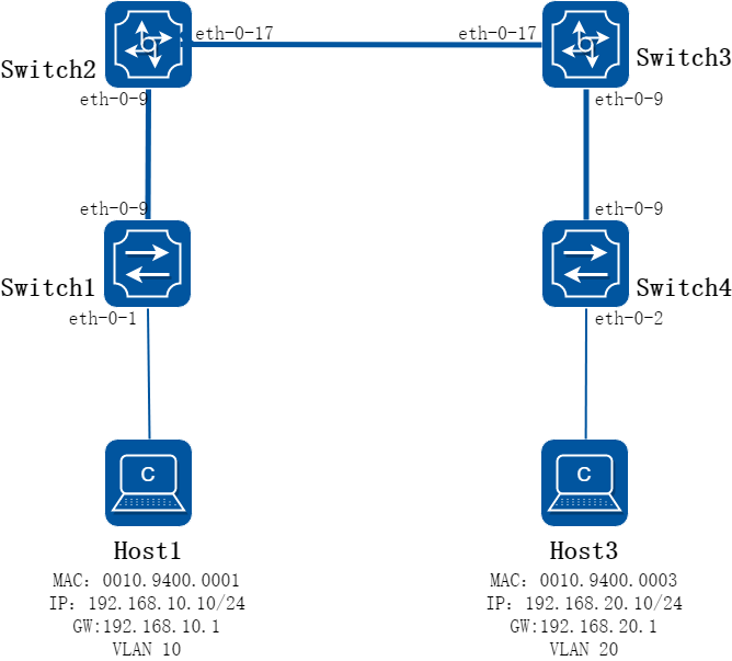
图17-49BGP EVPN引入外部路由
2.组网需求
如上图所示,Switch 2与Switch 3属于公网,Switch 1与Switch 4属于用户私网,分别下联两个网段的主机,并作为该网段主机的网关,两个网段都属于同一用户需要路由互通,因此考虑在Switch 2与Switch 3之间建立VXLAN隧道,将私网路由通过vxlan隧道来进行传输
3.配置思路
Switch 1与Switch 2,Switch 3与Switch 4分别使用IBGP在vrf下建立邻居,发布私网路由,Switch 2与Switch 3之间建立EBGP邻居,用于建立VXLAN隧道,同时将学习到的IBGP私网路由引入BGP EVPN中通告出去,使得Switch 1和Switch 4能相互学习到对端的网段路由。
4.配置步骤
步骤 1配置私网,建立私网路由
配置Switch 1
Switch1# configure terminal
Enter configuration commands, one per line. End with CNTL/Z.
Switch1(config)# ip vrf evpn
Switch1(config-vrf)# rd 1000:1
Switch1(config-vrf)# exit
Switch1(config)# interface eth-0-9
Switch1(config-if)# no switchport
Switch1(config-if)# ip vrf forwarding evpn
Switch1(config-if)# ip address 192.168.1.1/24
Switch1(config-if)# no shutdown
Switch1(config-if)# quit
Switch1(config)# vlan database
Switch1(config-vlan)# vlan 10
Switch1(config-vlan)# quit
Switch1(config)# interface vlan 10
Switch1(config-if)# ip vrf forwarding evpn
Switch1(config-if)# ip address 192.168.10.1/24
Switch1(config-if)# quit
Switch1(config)# interface eth-0-1
Switch1(config-if)# switchport mode trunk
Switch1(config-if)# switchport trunk allowed vlan add 10
Switch1(config-if)# no shutdown
Switch1(config-if)# quit
Switch1(config)# router bgp 100
Switch1(config-router)# address-family ipv4 vrf evpn
Switch1(config-router-af)# network 192.168.10.0 mask 255.255.255.0
Switch1(config-router-af)# neighbor 192.168.1.2 remote-as 100
Switch1(config-router-af)# neighbor 192.168.1.2 activate
Switch1(config-router)# end
配置Switch 2
Switch2# configure terminal
Enter configuration commands, one per line. End with CNTL/Z.
Switch2(config)# ip vrf evpn
Switch2(config-vrf)# rd 1000:2
Switch2(config-vrf)# vxlan vni 1000
Switch2(config-vrf)# qui
Switch2(config)# interface eth-0-9
Switch2(config-if)# no switchport
Switch2(config-if)# ip vrf forwarding evpn
Switch2(config-if)# ip address 192.168.1.2/24
Switch2(config-if)# no shutdown
Switch2(config-if)# quit
Switch2(config)# router bgp 100
Switch2(config-router)# address-family IPv4 vrf evpn
Switch2(config-router-af)# advertise l2vpn evpn
Switch2(config-router-af)# neighbor 192.168.1.1 remote-as 100
Switch2(config-router-af)# neighbor 192.168.1.1 activate
Switch2(config-router)# end
配置Switch 3
Switch3# configure terminal
Enter configuration commands, one per line. End with CNTL/Z.
Switch3(config)# ip vrf evpn
Switch3(config-vrf)# rd 1000:3
Switch3(config-vrf)# vxlan vni 1000
Switch3(config-vrf)# quit
Switch3(config)# interface eth-0-9
Switch3(config-if)# no switchport
Switch3(config-if)# ip vrf forwarding evpn
Switch3(config-if)# ip address 192.168.2.2/24
Switch3(config-if)# no shutdown
Switch3(config-if)# quit
Switch3(config)# router bgp 200
Switch3(config-router)# address-family ipv4 vrf evpn
Switch3(config-router-af)# advertise l2vpn evpn
Switch3(config-router-af)# neighbor 192.168.2.1 remote-as 200
Switch3(config-router-af)# neighbor 192.168.2.1 activate
Switch3(config-router)# end
配置Switch 4
Switch4# configure terminal
Enter configuration commands, one per line. End with CNTL/Z.
Switch4(config)# ip vrf evpn
Switch4(config-vrf)# rd 1000:4
Switch4(config-vrf)# qui
Switch4(config)# interface eth-0-9
Switch4(config-if)# no switchport
Switch4(config-if)# ip vrf forwarding evpn
Switch4(config-if)# ip address 192.168.2.1/24
Switch4(config-if)# no shutdown
Switch4(config-if)# exit
Switch4(config)# vlan database
Switch4(config-vlan)# vlan 20
Switch4(config-vlan)# quit
Switch4(config)# interface vlan 20
Switch4(config-if)# ip vrf forwarding evpn
Switch4(config-if)# ip address 192.168.20.1/24
Switch4(config-if)# quit
Switch4(config)# interface eth-0-1
Switch4(config-if)# switchport mode trunk
Switch4(config-if)# switchport trunk allowed vlan add 20
Switch4(config-if)# no shutdown
Switch4(config-if)# quit
Switch4(config)# router bgp 200
Switch4(config-router)# address-family ipv4 vrf evpn
Switch4(config-router-af)# network 192.168.20.0 mask 255.255.255.0
Switch4(config-router-af)# neighbor 192.168.2.2 remote-as 200
Switch4(config-router-af)# neighbor 192.168.2.2 activate
Switch4(config-router)# end
步骤 2配置BGP,建立BGP evpn邻居
配置Switch 2
Switch2# configure terminal
Enter configuration commands, one per line. End with CNTL/Z.
Switch2(config)# ip vrf evpn
Switch2(config-vrf)# route-target both 1000:1000 evpn
Switch2(config-vrf)# quit
Switch2(config)# interface eth-0-17
Switch2(config-if)# no switchport
Switch2(config-if)# ip address 192.168.17.1/24
Switch2(config-if)# no shutdown
Switch2(config-if)# vxlan uplink enable
Switch2(config-if)# quit
Switch2(config)# interface loopback 0
Switch2(config-if)# ip address 10.2.2.2/32
Switch2(config-if)# quit
Switch2(config)# ip route 10.3.3.3/32 192.168.17.2
Switch2(config)# evpn
Switch2(config-evpn)# exit
Switch2(config)# interface nve 0
Switch2(config-if)# source loopback 0
Switch2(config-if)# member vni 1000 associate-vrf
Switch2(config-if)# quit
Switch2(config)# router bgp 100
Switch2(config-router)# bgp router-id 10.2.2.2
Switch2(config-router)# neighbor 10.3.3.3 remote-as 200
Switch2(config-router)# neighbor 10.3.3.3 update-source loopback 0
Switch2(config-router)# neighbor 10.3.3.3 ebgp-multihop 255
Switch2(config-router)# address-family l2vpn evpn
Switch2(config-router-af)# neighbor 10.3.3.3 activate
Switch2(config-router-af)# neighbor 10.3.3.3 send-community both
Switch2(config-router-af)# end
配置Switch 3
Switch3# configure terminal
Enter configuration commands, one per line. End with CNTL/Z.
Switch3(config)# ip vrf evpn
Switch3(config-vrf)# route-target both 1000:1000 evpn
Switch3(config-vrf)# quit
Switch3(config)# interface eth-0-17
Switch3(config-if)# no switchport
Switch3(config-if)# ip address 192.168.17.2/24
Switch3(config-if)# no shutdown
Switch3(config-if)# vxlan uplink enable
Switch3(config-if)# quit
Switch3(config)# interface loopback 0
Switch3(config-if)# ip address 10.3.3.3/32
Switch3(config-if)# qui
Switch3(config)# ip route 10.2.2.2/32 192.168.17.1
Switch3(config)# evpn
Switch3(config-evpn)# exit
Switch3(config)# interface nve 0
Switch3(config-if)# source loopback 0
Switch3(config-if)# member vni 1000 associate-vrf
Switch3(config-if)# quit
Switch3(config)# router bgp 200
Switch3(config-router)# bgp router-id 10.3.3.3
Switch3(config-router)# neighbor 10.2.2.2 remote-as 100
Switch3(config-router)# neighbor 10.2.2.2 update-source loopback 0
Switch3(config-router)# neighbor 10.2.2.2 ebgp-multihop 255
Switch3(config-router)# address-family l2vpn evpn
Switch3(config-router-af)# neighbor 10.2.2.2 activate
Switch3(config-router-af)# neighbor 10.2.2.2 send-community both
Switch3(config-router-af)# end
步骤 3验证配置结果
Switch1上能学到远端的路由
Switch1# show ip bgp vpnv4 vrf evpn
BGP table version is 1, local router ID is 192.168.10.1
Status codes: s suppressed, d damped, h history, * valid, > best, i - inter
nal,
S Stale
Origin codes: i - IGP, e - EGP, ? - incomplete
Network Next Hop Metric LocPrf Weight Path
Route Distinguisher: 1000:1 (Default for VRF evpn)
*> 192.168.10.0/24 0.0.0.0 100 32768 i
*>i192.168.20.0/24 192.168.1.2 0 100 0 200 i
Switch1#
Switch1# show ip route vrf evpn
Codes: K - kernel, C - connected, S - static, R - RIP, B - BGP
O - OSPF, IA - OSPF inter area
N1 - OSPF NSSA external type 1, N2 - OSPF NSSA external type 2
E1 - OSPF external type 1, E2 - OSPF external type 2
i - IS-IS, L1 - IS-IS level-1, L2 - IS-IS level-2, ia - IS-IS inter
area
Dc - DHCP Client
[*] - [AD/Metric]
* - candidate default
C 192.168.1.0/24 is directly connected, eth-0-9
C 192.168.1.1/32 is in local loopback, eth-0-9
C 192.168.10.0/24 is directly connected, vlan10
C 192.168.10.1/32 is in local loopback, vlan10
B 192.168.20.0/24 [200/0] via 192.168.1.2, eth-0-9, 00:04:55
Switch4上能学到远端的路由
Switch4# show ip bgp vpnv4 vrf evpn
BGP table version is 1, local router ID is 192.168.20.1
Status codes: s suppressed, d damped, h history, * valid, > best, i - internal,
S Stale
Origin codes: i - IGP, e - EGP, ? - incomplete
Network Next Hop Metric LocPrf Weight Path
Route Distinguisher: 1000:4 (Default for VRF evpn)
*>i192.168.10.0/24 192.168.2.2 0 100 0 100 i
*> 192.168.20.0/24 0.0.0.0 100 32768 i
Switch4#
Switch4# show ip route vrf evpn
Codes: K - kernel, C - connected, S - static, R - RIP, B - BGP
O - OSPF, IA - OSPF inter area
N1 - OSPF NSSA external type 1, N2 - OSPF NSSA external type 2
E1 - OSPF external type 1, E2 - OSPF external type 2
i - IS-IS, L1 - IS-IS level-1, L2 - IS-IS level-2, ia - IS-IS inter area
Dc - DHCP Client
[*] - [AD/Metric]
* - candidate default
C 192.168.2.0/24 is directly connected, eth-0-9
C 192.168.2.1/32 is in local loopback, eth-0-9
B 192.168.10.0/24 [200/0] via 192.168.2.2, eth-0-9, 00:07:34
C 192.168.20.0/24 is directly connected, vlan20
C 192.168.20.1/32 is in local loopback, vlan20
Host 1与Host 3 互通
PING 192.168.20.10 from 192.168.10.10: 56 data bytes
64 bytes from 192.168.20.10: icmp_seq=1 ttl=60 time=0.730 ms
--- ping statistics ---
1 packets transmitted, 1 packets received, 0.0% packet loss
rtt min/avg/max/stddev = 0.730/0.730/0.730/0.000 ms
BGP EVPN方式部署分段式VXLAN隧道
1.组网拓扑
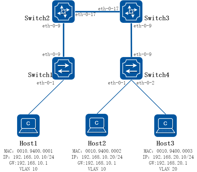
图17-50BGP EVPN方式部署分段式VXLAN隧道
2.组网需求
如上图所示,HOST1、2、3都属于租户test,其间既有相同网段又有不同网段,且都需要相互通信。Switch 2/3作为边界设备,隧道需要分段的建立,即Switch 1与Switch 2,Switch 2与Switch 3,Switch 3与Switch 4之间的VXLAN隧道,最终完成Host之间的互通
3.配置思路
SWITCH之间互相建立EBGP邻居,将发布路由的下一跳信息修改为自己的本地地址,以达成分段建立VXLAN隧道的目的,同时由于默认情况下隧道间由于水平分割的存在不会相互转发二层流量,因此需要在Switch 2和Switch 3上关闭水平分割。
4.配置步骤
步骤 1配置路由,保证交换机之间三层网络可通
配置Switch 1
Switch1# configure terminal
Enter configuration commands, one per line. End with CNTL/Z.
Switch1(config)# interface loopback 0
Switch1(config-if)# ip address 10.1.1.1/32
Switch1(config-if)# exit
Switch1(config)# interface eth-0-9
Switch1(config-if)# no switchport
Switch1(config-if)# ip address 192.168.1.1/24
Switch1(config-if)# vxlan uplink enable
Switch1(config-if)# no shutdown
Switch1(config-if)# exit
Switch1(config)# ip route 10.2.2.2/32 192.168.1.2
Switch1(config)# ip route 10.3.3.3/32 192.168.1.2
Switch1(config)# ip route 10.4.4.4/32 192.168.1.2
Switch1(config)# end
配置Switch 2
Switch2# configure terminal
Enter configuration commands, one per line. End with CNTL/Z.
Switch2(config)# interface loopback 0
Switch2(config-if)# ip address 10.2.2.2/32
Switch2(config-if)# exit
Switch2(config)# interface eth-0-9
Switch2(config-if)# no switchport
Switch2(config-if)# ip address 192.168.1.2/24
Switch2(config-if)# vxlan uplink enable
Switch2(config-if)# no shutdown
Switch2(config-if)# exit
Switch2(config)# interface eth-0-17
Switch2(config-if)# no switchport
Switch2(config-if)# ip address 192.168.2.1/24
Switch2(config-if)# vxlan uplink enable
Switch2(config-if)# no shutdown
Switch2(config-if)# exit
Switch2(config)# ip route 10.1.1.1/32 192.168.1.1
Switch2(config)# ip route 10.3.3.3/32 192.168.2.2
Switch2(config)# ip route 10.4.4.4/32 192.168.2.2
Switch2(config)# end
配置Switch 3
Switch3# configure terminal
Enter configuration commands, one per line. End with CNTL/Z.
Switch3(config)# interface loopback 0
Switch3(config-if)# ip address 10.3.3.3/32
Switch3(config-if)# exit
Switch3(config)# interface eth-0-9
Switch3(config-if)# no switchport
Switch3(config-if)# ip address 192.168.3.1/24
Switch3(config-if)# vxlan uplink enable
Switch3(config-if)# no shutdown
Switch3(config-if)# exit
Switch3(config)# interface eth-0-17
Switch3(config-if)# no switchport
Switch3(config-if)# ip address 192.168.2.2/24
Switch3(config-if)# vxlan uplink enable
Switch3(config-if)# no shutdown
Switch3(config-if)# exit
Switch3(config)# ip route 10.1.1.1/32 192.168.2.1
Switch3(config)# ip route 10.2.2.2/32 192.168.2.1
Switch3(config)# ip route 10.4.4.4/32 192.168.3.2
Switch3(config)# end
配置Switch 4
Switch4# configure terminal
Enter configuration commands, one per line. End with CNTL/Z.
Switch4(config)# interface loopback 0
Switch4(config-if)# ip address 10.4.4.4/32
Switch4(config-if)# exit
Switch4(config)# interface eth-0-9
Switch4(config-if)# no switchport
Switch4(config-if)# ip address 192.168.3.2/24
Switch4(config-if)# vxlan uplink enable
Switch4(config-if)# no shutdown
Switch4(config-if)# exit
Switch4(config)# ip route 10.1.1.1/32 192.168.3.1
Switch4(config)# ip route 10.2.2.2/32 192.168.3.1
Switch4(config)# ip route 10.3.3.3/32 192.168.3.1
Switch4(config)# end
步骤 2配置VLAN
配置Switch 1
Switch1# configure terminal
Enter configuration commands, one per line. End with CNTL/Z.
Switch1(config)# vlan database
Switch1(config-vlan)# vlan 10
Switch1(config-vlan)# vlan 10 overlay enable
Switch1(config-vlan)# exit
Switch1(config)# interface eth-0-1
Switch1(config-if)# switchport mode trunk
Switch1(config-if)# switchport trunk allowed vlan add 10
Switch1(config-if)# no shutdown
Switch1(config-if)# end
配置Switch 4
Switch4# configure terminal
Enter configuration commands, one per line. End with CNTL/Z.
Switch4(config)# vlan database
Switch4(config-vlan)# vlan 10,20
Switch4(config-vlan)# vlan 10 overlay enable
Switch4(config-vlan)# vlan 20 overlay enable
Switch4(config-vlan)# exit
Switch4(config)# interface eth-0-1
Switch4(config-if)# switchport mode trunk
Switch4(config-if)# switchport trunk allowed vlan add 10
Switch4(config-if)# no shutdown
Switch4(config-if)# exit
Switch4(config)# interface eth-0-2
Switch4(config-if)# switchport mode trunk
Switch4(config-if)# switchport trunk allowed vlan add 20
Switch4(config-if)# no shutdown
Switch4(config-if)# end
步骤 3配置分布式网关
配置Switch 1
Switch1# configure terminal
Enter configuration commands, one per line. End with CNTL/Z.
Switch1(config)# ip vrf evpn
Switch1(config-vrf)# rd 1000:1
Switch1(config-vrf)# route-target import 1000:1000 evpn
Switch1(config-vrf)# vxlan vni 1000
Switch1(config-vrf)# exit
Switch1(config)# interface vlan 10
Switch1(config-if)# ip vrf forwarding evpn
Switch1(config-if)# overlay distributed-gateway enable
Switch1(config-if)# ip address 192.168.10.1/24
Switch1(config-if)# end
配置Switch 2
Switch2# configure terminal
Enter configuration commands, one per line. End with CNTL/Z.
Switch2(config)# ip vrf evpn
Switch2(config-vrf)# rd 1000:2
Switch2(config-vrf)# route-target import 1000:1000 evpn
Switch2(config-vrf)# vxlan vni 1000
Switch2(config-vrf)# end
配置Switch 3
Switch3# configure terminal
Enter configuration commands, one per line. End with CNTL/Z.
Switch3(config)# ip vrf evpn
Switch3(config-vrf)# rd 1000:3
Switch3(config-vrf)# route-target import 1000:1000 evpn
Switch3(config-vrf)# vxlan vni 1000
Switch3(config-vrf)# end
Switch3#
配置Switch 4
Switch4# configure terminal
Enter configuration commands, one per line. End with CNTL/Z.
Switch4(config)# ip vrf evpn
Switch4(config-vrf)# rd 1000:4
Switch4(config-vrf)# route-target import 1000:1000 evpn
Switch4(config-vrf)# vxlan vni 1000
Switch4(config-vrf)# exit
Switch4(config)# interface vlan 10
Switch4(config-if)# ip vrf forwarding evpn
Switch4(config-if)# overlay distributed-gateway enable
Switch4(config-if)# ip address 192.168.10.1/24
Switch4(config-if)# exit
Switch4(config)# interface vlan 20
Switch4(config-if)# ip vrf forwarding evpn
Switch4(config-if)# overlay distributed-gateway enable
Switch4(config-if)# ip address 192.168.20.1/24
Switch4(config-if)# end
步骤 4配置BGP
配置Switch 1
Switch1# configure terminal
Enter configuration commands, one per line. End with CNTL/Z.
Switch1(config)# evpn
Switch1(config-evpn)# exit
Switch1(config)# router bgp 100
Switch1(config-router)# bgp router-id 10.1.1.1
Switch1(config-router)# neighbor 10.2.2.2 remote-as 101
Switch1(config-router)# neighbor 10.2.2.2 ebgp-multihop 255
Switch1(config-router)# neighbor 10.2.2.2 update-source loopback 0
Switch1(config-router)# address-family l2vpn evpn
Switch1(config-router-af)# neighbor 10.2.2.2 activate
Switch1(config-router-af)# neighbor 10.2.2.2 send-community both
Switch1(config-router-af)# end
配置Switch 2
Switch2# configure terminal
Enter configuration commands, one per line. End with CNTL/Z.
Switch2(config)# evpn
Switch2(config-evpn)# exit
Switch2(config)# router bgp 101
Switch2(config-router)# bgp router-id 10.2.2.2
Switch2(config-router)# neighbor 10.1.1.1 remote-as 100
Switch2(config-router)# neighbor 10.1.1.1 ebgp-multihop 255
Switch2(config-router)# neighbor 10.1.1.1 update-source loopback 0
Switch2(config-router)# neighbor 10.3.3.3 remote-as 201
Switch2(config-router)# neighbor 10.3.3.3 ebgp-multihop 255
Switch2(config-router)# neighbor 10.3.3.3 update-source loopback 0
Switch2(config-router)# address-family l2vpn evpn
Switch2(config-router-af)# neighbor 10.1.1.1 activate
Switch2(config-router-af)# neighbor 10.1.1.1 send-community both
Switch2(config-router-af)# neighbor 10.3.3.3 activate
Switch2(config-router-af)# neighbor 10.3.3.3 send-community both
Switch2(config-router-af)# end
配置Switch 3
Switch3# configure terminal
Enter configuration commands, one per line. End with CNTL/Z.
Switch3(config)# evpn
Switch3(config-evpn)# exit
Switch3(config)# router bgp 201
Switch3(config-router)# bgp router-id 10.3.3.3
Switch3(config-router)# neighbor 10.2.2.2 remote-as 101
Switch3(config-router)# neighbor 10.2.2.2 ebgp-multihop 255
Switch3(config-router)# neighbor 10.2.2.2 update-source loopback 0
Switch3(config-router)# neighbor 10.4.4.4 remote-as 200
Switch3(config-router)# neighbor 10.4.4.4 ebgp-multihop 255
Switch3(config-router)# neighbor 10.4.4.4 update-source loopback0
Switch3(config-router)# address-family l2vpn evpn
Switch3(config-router-af)# neighbor 10.2.2.2 activate
Switch3(config-router-af)# neighbor 10.2.2.2 send-community both
Switch3(config-router-af)# neighbor 10.4.4.4 activate
Switch3(config-router-af)# neighbor 10.4.4.4 send-community both
Switch3(config-router-af)# end
配置Switch 4
Switch4# configure terminal
Enter configuration commands, one per line. End with CNTL/Z.
Switch4(config)# evpn
Switch4(config-evpn)# exit
Switch4(config)# router bgp 200
Switch4(config-router)# bgp router-id 10.4.4.4
Switch4(config-router)# neighbor 10.3.3.3 remote-as 201
Switch4(config-router)# neighbor 10.3.3.3 ebgp-multihop 255
Switch4(config-router)# neighbor 10.3.3.3 update-source loopback 0
Switch4(config-router)# address-family l2vpn evpn
Switch4(config-router-af)# neighbor 10.3.3.3 activate
Switch4(config-router-af)# neighbor 10.3.3.3 send-community both
Switch4(config-router-af)# end
步骤 5配置EVPN实例,并使能发布irb路由
配置Switch 1
Switch1# configure terminal
Enter configuration commands, one per line. End with CNTL/Z.
Switch1(config)# overlay
Switch1(config-overlay)# vlan 10 vni 10
Switch1(config-overlay)# quit
Switch1(config)# interface nve 0
Switch1(config-if)# source loopback 0
Switch1(config-if)# member vni 10
Switch1(config-if)# member vni 1000 associate-vrf
Switch1(config-if)# quit
Switch1(config)# evpn
Switch1(config-evpn)# vni 10
Switch1(config-evi)# rd 10:1
Switch1(config-evi)# route-target both 10:10
Switch1(config-evi)# route-target export 1000:1000
Switch1(config-evi)# quit
Switch1(config-evpn)# quit
Switch1(config)# interface vlan 10
Switch1(config-if)# overlay host-collect enable
Switch1(config-evpn)# end
配置Switch 2
Switch2# configure terminal
Enter configuration commands, one per line. End with CNTL/Z.
Switch2(config)# interface nve 0
Switch2(config-if)# source loopback 0
Switch2(config-if)# member vni 1000 associate-vrf
Switch2(config-if)# end
配置Switch 3
Switch3# configure terminal
Enter configuration commands, one per line. End with CNTL/Z.
Switch3(config)# interface nve 0
Switch3(config-if)# source loopback 0
Switch3(config-if)# member vni 1000 associate-vrf
Switch3(config-if)# end
配置Switch 4
Switch4# configure terminal
Enter configuration commands, one per line. End with CNTL/Z.
Switch4(config)# overlay
Switch4(config-overlay)# vlan 10 vni 10
Switch4(config-overlay)# vlan 20 vni 20
Switch4(config-overlay)# exit
Switch4(config)# interface nve 0
Switch4(config-if)# source loopback 0
Switch4(config-if)# member vni 10
Switch4(config-if)# member vni 20
Switch4(config-if)# member vni 1000 associate-vrf
Switch4(config-if)# quit
Switch4(config)# evpn
Switch4(config-evpn)# vni 10
Switch4(config-evi)# rd 10:4
Switch4(config-evi)# route-target both 10:10
Switch4(config-evi)# route-target export 1000:1000
Switch4(config-evi)# vni 20
Switch4(config-evi)# rd 20:4
Switch4(config-evi)# route-target both 20:20
Switch4(config-evi)# route-target export 1000:1000
Switch4(config-evi)# end
Switch4# configure terminal
Enter configuration commands, one per line. End with CNTL/Z.
Switch4(config)# interface vlan 10
Switch4(config-if)# overlay host-collect enable
Switch4(config-if)# interface vlan 20
Switch4(config-if)# overlay host-collect enable
Switch4(config-if)# end
步骤 6配置EVPN实例,关闭水平分割
配置Switch 2
Switch2# configure terminal
Enter configuration commands, one per line. End with CNTL/Z.
Switch2(config)# vlan database
Switch2(config-vlan)# vlan 10
Switch2(config-vlan)# vlan 10 overlay enable
Switch2(config-vlan)# exit
Switch2(config)# overlay
Switch2(config-overlay)# vlan 10 vni 10
Switch2(config-overlay)# exit
Switch2(config)# evpn
Switch2(config-evpn)# vni 10
Switch2(config-evi)# rd 10:2
Switch2(config-evi)# route-target import 1000:1000
Switch2(config-evi)# exit
Switch2(config-evpn)# exit
Switch2(config)# interface nve 0
Switch2(config-if)# member vni 10
Switch2(config-if)# split-horizon disable
Switch2(config-if)# end
Switch2# clear bgp evpn *
配置Switch 3
Switch3# configure terminal
Enter configuration commands, one per line. End with CNTL/Z.
Switch3(config)# vlan database
Switch3(config-vlan)# vlan 10
Switch3(config-vlan)# vlan 10 overlay enable
Switch3(config-vlan)# exit
Switch3(config)# overlay
Switch3(config-overlay)# vlan 10 vni 10
Switch3(config-overlay)# exit
Switch3(config)# evpn
Switch3(config-evpn)# vni 10
Switch3(config-evi)# rd 10:3
Switch3(config-evi)# route-target import 1000:1000
Switch3(config-evi)# exit
Switch3(config-evpn)# exit
Switch3(config)# interface nve 0
Switch3(config-if)# member vni 10
Switch3(config-if)# split-horizon disable
Switch3(config-if)# end
Switch3# clear bgp evpn *
步骤 7验证配置结果
Switch1:
Switch1# show mac address-table
MAC Address Table
-------------------------------------------
(*) - Security Entry (M) - MLAG Entry
(MO) - MLAG Output Entry (MI) - MLAG Input Entry
(E) - EVPN Entry (EO) - EVPN Output Entry
(EI) - EVPN Input Entry
Vlan MAC Address Type Ports
---- ----------- -------- -----
10 0010.9400.0002 dynamic VxLAN: 10.1.1.1->10.2.2.2(EI)
10 0010.9400.0001 dynamic eth-0-1(EO)
Switch1# show ip route vrf evpn
Codes: K - kernel, C - connected, S - static, R - RIP, B - BGP
O - OSPF, IA - OSPF inter area
N1 - OSPF NSSA external type 1, N2 - OSPF NSSA external type 2
E1 - OSPF external type 1, E2 - OSPF external type 2
i - IS-IS, L1 - IS-IS level-1, L2 - IS-IS level-2, ia - IS-IS inter area
Dc - DHCP Client
[*] - [AD/Metric]
* - candidate default
C 192.168.10.0/24 is directly connected, vlan10
C 192.168.10.1/32 is in local loopback, vlan10
B 192.168.10.20/32 [20/0] is in overlay remote vxlan vtep:10.1.1.1->10.2.2.2, vni:1000
B 192.168.20.10/32 [20/0] is in overlay remote vxlan vtep:10.1.1.1->10.2.2.2, vni:1000
Switch1# show ip arp vrf evpn
Protocol Address Age (min) Hardware Addr Interface
Internet 192.168.10.1 - 001e.080a.73d6 vlan10
Internet 192.168.10.10 1 0010.9400.0001 vlan10
Switch2:
Switch2# show mac address-table
MAC Address Table
-------------------------------------------
(*) - Security Entry (M) - MLAG Entry
(MO) - MLAG Output Entry (MI) - MLAG Input Entry
(E) - EVPN Entry (EO) - EVPN Output Entry
(EI) - EVPN Input Entry
Vlan MAC Address Type Ports
---- ----------- -------- -----
10 0010.9400.0002 dynamic VxLAN: 10.2.2.2->10.3.3.3(EI)
10 0010.9400.0001 dynamic VxLAN: 10.2.2.2->10.1.1.1(EI)
Switch2# show ip route vrf evpn
Codes: K - kernel, C - connected, S - static, R - RIP, B - BGP
O - OSPF, IA - OSPF inter area
N1 - OSPF NSSA external type 1, N2 - OSPF NSSA external type 2
E1 - OSPF external type 1, E2 - OSPF external type 2
i - IS-IS, L1 - IS-IS level-1, L2 - IS-IS level-2, ia - IS-IS inter area
Dc - DHCP Client
[*] - [AD/Metric]
* - candidate default
B 192.168.10.10/32 [20/0] is in overlay remote vxlan vtep:10.2.2.2->10.1.1.1, vni:1000
B 192.168.10.20/32 [20/0] is in overlay remote vxlan vtep:10.2.2.2->10.3.3.3, vni:1000
B 192.168.20.10/32 [20/0] is in overlay remote vxlan vtep:10.2.2.2->10.3.3.3, vni:1000
Switch3:
Switch3# show mac address-table
MAC Address Table
-------------------------------------------
(*) - Security Entry (M) - MLAG Entry
(MO) - MLAG Output Entry (MI) - MLAG Input Entry
(E) - EVPN Entry (EO) - EVPN Output Entry
(EI) - EVPN Input Entry
Vlan MAC Address Type Ports
---- ----------- -------- -----
10 0010.9400.0001 dynamic VxLAN: 10.3.3.3->10.2.2.2(EI)
10 0010.9400.0002 dynamic VxLAN: 10.3.3.3->10.4.4.4(EI)
Switch3# show ip route vrf evpn
Codes: K - kernel, C - connected, S - static, R - RIP, B - BGP
O - OSPF, IA - OSPF inter area
N1 - OSPF NSSA external type 1, N2 - OSPF NSSA external type 2
E1 - OSPF external type 1, E2 - OSPF external type 2
i - IS-IS, L1 - IS-IS level-1, L2 - IS-IS level-2, ia - IS-IS inter area
Dc - DHCP Client
[*] - [AD/Metric]
* - candidate default
B 192.168.10.10/32 [20/0] is in overlay remote vxlan vtep:10.3.3.3->10.2.2.2, vni:1000
B 192.168.10.20/32 [20/0] is in overlay remote vxlan vtep:10.3.3.3->10.4.4.4, vni:1000
B 192.168.20.10/32 [20/0] is in overlay remote vxlan vtep:10.3.3.3->10.4.4.4, vni:1000
Switch4:
Switch4# show mac address-table
MAC Address Table
-------------------------------------------
(*) - Security Entry (M) - MLAG Entry
(MO) - MLAG Output Entry (MI) - MLAG Input Entry
(E) - EVPN Entry (EO) - EVPN Output Entry
(EI) - EVPN Input Entry
Vlan MAC Address Type Ports
---- ----------- -------- -----
20 0010.9400.0003 dynamic eth-0-2(EO)
10 0010.9400.0001 dynamic VxLAN: 10.4.4.4->10.3.3.3(EI)
10 0010.9400.0002 dynamic eth-0-1(EO)
Switch4# show ip arp vrf evpn
Protocol Address Age (min) Hardware Addr Interface
Internet 192.168.10.1 - 001e.080a.72ae vlan10
Internet 192.168.10.20 4 0010.9400.0002 vlan10
Internet 192.168.20.1 - 001e.080a.72ae vlan20
Internet 192.168.20.10 4 0010.9400.0003 vlan20
Switch4# show ip route vrf evpn
Codes: K - kernel, C - connected, S - static, R - RIP, B - BGP
O - OSPF, IA - OSPF inter area
N1 - OSPF NSSA external type 1, N2 - OSPF NSSA external type 2
E1 - OSPF external type 1, E2 - OSPF external type 2
i - IS-IS, L1 - IS-IS level-1, L2 - IS-IS level-2, ia - IS-IS inter area
Dc - DHCP Client
[*] - [AD/Metric]
* - candidate default
C 192.168.10.0/24 is directly connected, vlan10
C 192.168.10.1/32 is in local loopback, vlan10
B 192.168.10.10/32 [20/0] is in overlay remote vxlan vtep:10.4.4.4->10.3.3.3, vni:1000
C 192.168.20.0/24 is directly connected, vlan20
C 192.168.20.1/32 is in local loopback, vlan20
MLAG设备作为TOR接入EVPN网络
1.组网拓扑
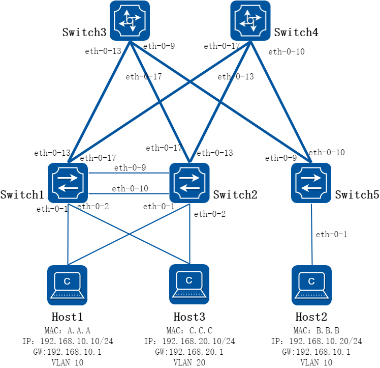
图17-51MLAG设备作为TOR接入EVPN网络
2.组网需求
3.组网需求
如上图所示,Switch 1/2/5作为TOR交换机,SWITCH 3/4作为Spine其间网络为三层网络,下联的HOST都属于同一用户,需求与其他用户隔离的同时保证相同网段/不同网段间的主机都能互通。为了保证可靠性,其中部分服务器需要双活接入。
4.配置思路
SWITCH 1/2上配置MLAG 并配置virtual ip作为服务器网关保证双活接入,同时为了保证虚拟机迁移后网关地址不变,在SWITH 1/2/5上部署分布式网关并使用相同的ip。使用IBGP构建EVPN网络,Switch 1和Switch 2使用相同的VTEP地址,对外表现为同一个VTEP,在Switch 3和Switch 4上使能路由反射器减少BGP邻居数量的同时,让SWITCH 1/2/5都能学到EVPN路由。
5.配置步骤
步骤 1配置MLAG
分别在Switch 1/2配置MLAG,用于服务器双活接入,Switch 5使用单接口下联。
配置peer-link
Switch1:
Switch1# configure terminal
Enter configuration commands, one per line. End with CNTL/Z.
Switch1(config)# interface range eth-0-9 to eth-0-10
Switch1(config-if-range)# no shutdown
Switch1(config-if-range)# static-channel-group 55
Switch1(config-if-range)# exit
Switch1(config)# interface agg 55
Switch1(config-if)# switchport mode trunk
Switch1(config-if)# switchport trunk allowed vlan all
Switch1(config-if)# spanning-tree port disable
Switch1(config-if)# exit
Switch1(config)# mlag configuration
Switch1(config-mlag)# peer-link agg 55
Switch1(config-mlag)# end
Switch2:
Switch2# configure terminal
Enter configuration commands, one per line. End with CNTL/Z.
Switch2(config)# interface range eth-0-9 to eth-0-10
Switch2(config-if-range)# no shutdown
Switch2(config-if-range)# static-channel-group 55
Switch2(config-if-range)# exit
Switch2(config)# interface agg 55
Switch2(config-if)# switchport mode trunk
Switch2(config-if)# switchport trunk allowed vlan all
Switch2(config-if)# spanning-tree port disable
Switch2(config-if)# exit
Switch2(config)# mlag configuration
Switch2(config-mlag)# peer-link agg 55
Switch2(config-mlag)# end
配置peer-address
Switch1:
Switch1# configure terminal
Enter configuration commands, one per line. End with CNTL/Z.
Switch1(config)# vlan database
Switch1(config-vlan)# vlan 4094
Switch1(config-vlan)# exit
Switch1(config)# interface vlan 4094
Switch1(config-if)# ip address 40.94.0.1/24
Switch1(config-if)# exit
Switch1(config)# mlag configuration
Switch1(config-mlag)# peer-address 40.94.0.2
Switch1(config-mlag)# end
Switch2:
Switch2# configure terminal
Enter configuration commands, one per line. End with CNTL/Z.
Switch2(config)# vlan database
Switch2(config-vlan)# vlan 4094
Switch2(config-vlan)# exit
Switch2(config)# interface vlan 4094
Switch2(config-if)# ip address 40.94.0.2/24
Switch2(config-if)# exit
Switch2(config)# mlag configuration
Switch2(config-mlag)# peer-address 40.94.0.1
Switch2(config-mlag)# end
配置下联接口
配置下联接口,SWITC 1/2使用MLAG双下联,Switch 5普通单下联。
Switch1:
Switch1# configure terminal
Enter configuration commands, one per line. End with CNTL/Z.
Switch1(config)# vlan database
Switch1(config-vlan)# vlan 10,20
Switch1(config-vlan)# exit
Switch1(config)# interface eth-0-1
Switch1(config-if)# switchport mode trunk
Switch1(config-if)# switchport trunk allowed vlan add 10
Switch1(config-if)# no shutdown
Switch1(config-if)# static-channel-group 1
Switch1(config-if)# exit
Switch1(config)# interface eth-0-2
Switch1(config-if)# switchport mode trunk
Switch1(config-if)# switchport trunk allowed vlan add 20
Switch1(config-if)# no shutdown
Switch1(config-if)# static-channel-group 2
Switch1(config-if)# exit
Switch1(config)# interface agg 1
Switch1(config-if)# mlag 1
Switch1(config-if)# exit
Switch1(config)# interface agg 2
Switch1(config-if)# mlag 2
Switch1(config-if)# end
Switch2:
Switch2# configure terminal
Enter configuration commands, one per line. End with CNTL/Z.
Switch2(config)# vlan database
Switch2(config-vlan)# vlan 10,20
Switch2(config-vlan)# exit
Switch2(config)# interface eth-0-1
Switch2(config-if)# switchport mode trunk
Switch2(config-if)# switchport trunk allowed vlan add 10
Switch2(config-if)# static-channel-group 1
Switch2(config-if)# no shutdown
Switch2(config-if)# exit
Switch2(config)# interface eth-0-2
Switch2(config-if)# switchport mode trunk
Switch2(config-if)# switchport trunk allowed vlan add 20
Switch2(config-if)# static-channel-group 2
Switch2(config-if)# no shutdown
Switch2(config-if)# exit
Switch2(config)# interface agg 1
Switch2(config-if)# mlag 1
Switch2(config-if)# exit
Switch2(config)# interface agg 2
Switch2(config-if)# mlag 2
Switch2(config-if)# end
Switch5:
Switch5# configure terminal
Enter configuration commands, one per line. End with CNTL/Z.
Switch5(config)# vlan database
Switch5(config-vlan)# vlan 10
Switch5(config-vlan)# exit
Switch5(config)# interface eth-0-1
Switch5(config-if)# switchport mode trunk
Switch5(config-if)# switchport trunk allowed vlan add 10
Switch5(config-if)# no shutdown
Switch5(config-if)# end
步骤 2配置网关地址并使能分布式网关,在MLAG设备上使用virtual ip
Switch1:
Switch1# configure terminal
Enter configuration commands, one per line. End with CNTL/Z.
Switch1(config)# ip vrf evpn
Switch1(config-vrf)# rd 1000:1
Switch1(config-vrf)# vxlan vni 1000
Switch1(config-vrf)# exit
Switch1(config)# interface vlan 10
Switch1(config-if)# ip vrf forwarding evpn
Switch1(config-if)# ip address 192.168.10.253/24
Switch1(config-if)# ip virtual-router address 192.168.10.1
Switch1(config-if)# overlay distributed-gateway enable
Switch1(config-if)# exit
Switch1(config)# interface vlan 20
Switch1(config-if)# ip vrf forwarding evpn
Switch1(config-if)# ip address 192.168.20.253/24
Switch1(config-if)# ip virtual-router address 192.168.20.1
Switch1(config-if)# overlay distributed-gateway enable
Switch1(config-if)# exit
Switch1(config)# ip virtual-router mac 0.0.1
Switch1(config)# end
Switch2:
Switch2# configure terminal
Enter configuration commands, one per line. End with CNTL/Z.
Switch2(config)# ip vrf evpn
Switch2(config-vrf)# rd 1000:2
Switch2(config-vrf)# vxlan vni 1000
Switch2(config-vrf)# exit
Switch2(config)# interface vlan 10
Switch2(config-if)# ip vrf forwarding evpn
Switch2(config-if)# ip address 192.168.10.254/24
Switch2(config-if)# ip virtual-router address 192.168.10.1
Switch2(config-if)# overlay distributed-gateway enable
Switch2(config-if)# exit
Switch2(config)# interface vlan 20
Switch2(config-if)# ip vrf forwarding evpn
Switch2(config-if)# ip address 192.168.20.254/24
Switch2(config-if)# ip virtual-router address 192.168.20.1
Switch2(config-if)# overlay distributed-gateway enable
Switch2(config-if)# exit
Switch2(config)# ip virtual-router mac 0.0.1
Switch2(config)# end
Switch5:
Switch5# configure terminal
Enter configuration commands, one per line. End with CNTL/Z.
Switch5(config)# ip vrf evpn
Switch5(config-vrf)# rd 1000:5
Switch5(config-vrf)# vxlan vni 1000
Switch5(config-vrf)# qui
Switch5(config)# interface vlan 10
Switch5(config-if)# ip vrf forwarding evpn
Switch5(config-if)# ip address 192.168.10.254/24
Switch5(config-if)# ip virtual-router address 192.168.10.1
Switch5(config-if)# overlay distributed-gateway enable
Switch5(config-if)# exit
Switch5(config)# ip virtual-router mac 0.0.2
Switch5(config)# end
步骤 3配置路由,保证交换机之间三层网络可通
Switch1:
Switch1# configure terminal
Enter configuration commands, one per line. End with CNTL/Z.
Switch1(config)# interface loopback 0
Switch1(config-if)# ip address 10.1.1.1/32
Switch1(config-if)# exit
Switch1(config)# interface loopback 1
Switch1(config-if)# ip address 10.11.11.11/32
Switch1(config-if)# exit
Switch1(config)# interface eth-0-13
Switch1(config-if)# no switchport
Switch1(config-if)# no shutdown
Switch1(config-if)# vxlan uplink enable
Switch1(config-if)# ip address 13.1.1.1/24
Switch1(config-if)# exit
Switch1(config)# interface eth-0-17
Switch1(config-if)# no switchport
Switch1(config-if)# no shutdown
Switch1(config-if)# vxlan uplink enable
Switch1(config-if)# ip address 17.1.1.1/24
Switch1(config-if)# exit
Switch1(config)# router ospf
Switch1(config-router)# router-id 10.1.1.1
Switch1(config-router)# network 10.1.1.1 0.0.0.0 area 0
Switch1(config-router)# network 10.11.11.11 0.0.0.0 area 0
Switch1(config-router)# network 13.1.1.0 0.0.0.255 area 0
Switch1(config-router)# network 17.1.1.0 0.0.0.255 area 0
Switch1(config)#end
Switch2:
Switch2# configure terminal
Enter configuration commands, one per line. End with CNTL/Z.
Switch2(config)# interface loopback 0
Switch2(config-if)# ip address 10.2.2.2/32
Switch2(config-if)# exit
Switch2(config)# interface loopback 1
Switch2(config-if)# ip address 10.11.11.11/32
Switch2(config-if)# exit
Switch2(config)# interface eth-0-13
Switch2(config-if)# no switchport
Switch2(config-if)# no shutdown
Switch2(config-if)# vxlan uplink enable
Switch2(config-if)# ip address 13.2.2.1/24
Switch2(config-if)# exit
Switch2(config)# interface eth-0-17
Switch2(config-if)# no switchport
Switch2(config-if)# no shutdown
Switch2(config-if)# vxlan uplink enable
Switch2(config-if)# ip address 17.2.2.1/24
Switch2(config-if)# exit
Switch2(config)# router ospf
Switch2(config-router)# router-id 10.2.2.2
Switch2(config-router)# network 10.2.2.2 0.0.0.0 area 0
Switch2(config-router)# network 10.11.11.11 0.0.0.0 area 0
Switch2(config-router)# network 13.2.2.0 0.0.0.255 area 0
Switch2(config-router)# network 17.2.2.0 0.0.0.255 area 0
Switch2(config)# end
Switch3:
Switch3# configure terminal
Enter configuration commands, one per line. End with CNTL/Z.
Switch3(config)# interface loopback 0
Switch3(config-if)# ip address 10.3.3.3/32
Switch3(config-if)# exit
Switch3(config)# interface eth-0-9
Switch3(config-if)# no shutdown
Switch3(config-if)# no switchport
Switch3(config-if)# ip address 9.1.1.2/24
Switch3(config-if)# exit
Switch3(config)# interface eth-0-13
Switch3(config-if)# no shutdown
Switch3(config-if)# no switchport
Switch3(config-if)# ip address 13.1.1.2/24
Switch3(config-if)# exit
Switch3(config)# interface eth-0-17
Switch3(config-if)# no shutdown
Switch3(config-if)# no switchport
Switch3(config-if)# ip address 17.2.2.2/24
Switch3(config-if)# exit
Switch3(config)# router ospf
Switch3(config-router)# router-id 10.3.3.3
Switch3(config-router)# network 9.1.1.0 0.0.0.255 area 0
Switch3(config-router)# network 13.1.1.0 0.0.0.255 area 0
Switch3(config-router)# network 17.2.2.0 0.0.0.255 area 0
Switch3(config-router)# network 10.3.3.3 0.0.0.0 area 0
Switch3(config)# end
Switch4:
Switch4# configure terminal
Enter configuration commands, one per line. End with CNTL/Z.
Switch4(config)# interface loopback 0
Switch4(config-if)# ip address 10.4.4.4/32
Switch4(config-if)# exit
Switch4(config)# interface eth-0-10
Switch4(config-if)# no shutdown
Switch4(config-if)# no switchport
Switch4(config-if)# ip address 10.10.10.2/24
Switch4(config-if)# exit
Switch4(config)# interface eth-0-13
Switch4(config-if)# no shutdown
Switch4(config-if)# no switchport
Switch4(config-if)# ip address 13.2.2.2/24
Switch4(config-if)# exit
Switch4(config)# interface eth-0-17
Switch4(config-if)# no shutdown
Switch4(config-if)# no switchport
Switch4(config-if)# ip address 17.1.1.2/24
Switch4(config-if)# exit
Switch4(config)# router ospf
Switch4(config-router)# router-id 10.4.4.4
Switch4(config-router)# network 10.10.10.0 0.0.0.255 area 0
Switch4(config-router)# network 13.2.2.0 0.0.0.255 area 0
Switch4(config-router)# network 17.1.1.0 0.0.0.255 area 0
Switch4(config-router)# network 10.4.4.4 0.0.0.0 area 0
Switch4(config)# end
Switch5:
Switch5# configure terminal
Enter configuration commands, one per line. End with CNTL/Z.
Switch5(config)# interface loopback 0
Switch5(config-if)# ip address 10.5.5.5/32
Switch5(config-if)# exit
Switch5(config)# interface eth-0-9
Switch5(config-if)# no switchport
Switch5(config-if)# no shutdown
Switch5(config-if)# vxlan uplink enable
Switch5(config-if)# ip address 9.1.1.1/24
Switch5(config-if)# exit
Switch5(config)# interface eth-0-10
Switch5(config-if)# no switchport
Switch5(config-if)# no shutdown
Switch5(config-if)# vxlan uplink enable
Switch5(config-if)# ip address 10.10.10.1/24
Switch5(config-if)# exit
Switch5(config)# router ospf
Switch5(config-router)# router-id 10.5.5.5
Switch5(config-router)# network 9.1.1.0 0.0.0.255 area 0
Switch5(config-router)# network 10.10.10.0 0.0.0.255 area 0
Switch5(config-router)# network 10.5.5.5 0.0.0.0 area 0
Switch5(config)#end
步骤 4配置BGP EVPN邻居
Switch1:
Switch1# configure terminal
Enter configuration commands, one per line. End with CNTL/Z.
Switch1(config)# evpn
Switch1(config-evpn)# exit
Switch1(config)# router bgp 100
Switch1(config-router)# bgp router-id 10.1.1.1
Switch1(config-router)# neighbor 10.3.3.3 remote-as 100
Switch1(config-router)# neighbor 10.3.3.3 update-source loopback 0
Switch1(config-router)# neighbor 10.4.4.4 remote-as 100
Switch1(config-router)# neighbor 10.4.4.4 update-source loopback 0
Switch1(config-router)# address-family l2vpn evpn
Switch1(config-router-af)# neighbor 10.3.3.3 activate
Switch1(config-router-af)# neighbor 10.3.3.3 send-community both
Switch1(config-router-af)# neighbor 10.4.4.4 activate
Switch1(config-router-af)# neighbor 10.4.4.4 send-community both
Switch1(config-router-af)# end
Switch2:
Switch2# configure terminal
Enter configuration commands, one per line. End with CNTL/Z.
Switch2(config)# evpn
Switch2(config-evpn)# exit
Switch2(config)# router bgp 100
Switch2(config-router)# bgp router-id 10.2.2.2
Switch2(config-router)# neighbor 10.3.3.3 remote-as 100
Switch2(config-router)# neighbor 10.3.3.3 update-source loopback0
Switch2(config-router)# neighbor 10.4.4.4 remote-as 100
Switch2(config-router)# neighbor 10.4.4.4 update-source loopback0
Switch2(config-router)# address-family l2vpn evpn
Switch2(config-router-af)# neighbor 10.3.3.3 activate
Switch2(config-router-af)# neighbor 10.3.3.3 send-community both
Switch2(config-router-af)# neighbor 10.4.4.4 activate
Switch2(config-router-af)# neighbor 10.4.4.4 send-community both
Switch2(config-router-af)# end
Switch3:
Switch3# configure terminal
Enter configuration commands, one per line. End with CNTL/Z.
Switch3(config)# evpn
Switch3(config-evpn)# exit
Switch3(config)# router bgp 100
Switch3(config-router)# bgp router-id 10.3.3.3
Switch3(config-router)# neighbor 10.1.1.1 remote-as 100
Switch3(config-router)# neighbor 10.1.1.1 update-source loopback 0
Switch3(config-router)# neighbor 10.2.2.2 remote-as 100
Switch3(config-router)# neighbor 10.2.2.2 update-source loopback 0
Switch3(config-router)# neighbor 10.5.5.5 remote-as 100
Switch3(config-router)# neighbor 10.5.5.5 update-source loopback 0
Switch3(config-router)# address-family l2vpn evpn
Switch3(config-router-af)# neighbor 10.1.1.1 activate
Switch3(config-router-af)# neighbor 10.1.1.1 send-community both
Switch3(config-router-af)# neighbor 10.1.1.1 route-reflector-client
Switch3(config-router-af)# neighbor 10.2.2.2 activate
Switch3(config-router-af)# neighbor 10.2.2.2 send-community both
Switch3(config-router-af)# neighbor 10.2.2.2 route-reflector-client
Switch3(config-router-af)# neighbor 10.5.5.5 activate
Switch3(config-router-af)# neighbor 10.5.5.5 send-community both
Switch3(config-router-af)# neighbor 10.5.5.5 route-reflector-client
Switch3(config-router-af)# end
Switch4:
Switch4# configure terminal
Enter configuration commands, one per line. End with CNTL/Z.
Switch4(config)# evpn
Switch4(config-evpn)# exit
Switch4(config)# router bgp 100
Switch4(config-router)# bgp router-id 10.4.4.4
Switch4(config-router)# neighbor 10.1.1.1 remote-as 100
Switch4(config-router)# neighbor 10.1.1.1 update-source loopback0
Switch4(config-router)# neighbor 10.2.2.2 remote-as 100
Switch4(config-router)# neighbor 10.2.2.2 update-source loopback0
Switch4(config-router)# neighbor 10.5.5.5 remote-as 100
Switch4(config-router)# neighbor 10.5.5.5 update-source loopback0
Switch4(config-router)# address-family l2vpn evpn
Switch4(config-router-af)# neighbor 10.1.1.1 activate
Switch4(config-router-af)# neighbor 10.1.1.1 route-reflector-client
Switch4(config-router-af)# neighbor 10.1.1.1 send-community both
Switch4(config-router-af)# neighbor 10.2.2.2 activate
Switch4(config-router-af)# neighbor 10.2.2.2 route-reflector-client
Switch4(config-router-af)# neighbor 10.2.2.2 send-community both
Switch4(config-router-af)# neighbor 10.5.5.5 activate
Switch4(config-router-af)# neighbor 10.5.5.5 route-reflector-client
Switch4(config-router-af)# neighbor 10.5.5.5 send-community both
Switch4(config-router-af)# end
Switch5:
Switch5# configure terminal
Enter configuration commands, one per line. End with CNTL/Z.
Switch5(config)# evpn
Switch5(config-evpn)# exit
Switch5(config)# router bgp 100
Switch5(config-router)# bgp router-id 10.5.5.5
Switch5(config-router)# neighbor 10.3.3.3 remote-as 100
Switch5(config-router)# neighbor 10.3.3.3 update-source loopback0
Switch5(config-router)# neighbor 10.4.4.4 remote-as 100
Switch5(config-router)# neighbor 10.4.4.4 update-source loopback0
Switch5(config-router)# address-family l2vpn evpn
Switch5(config-router-af)# neighbor 10.3.3.3 activate
Switch5(config-router-af)# neighbor 10.3.3.3 send-community both
Switch5(config-router-af)# neighbor 10.4.4.4 activate
Switch5(config-router-af)# neighbor 10.4.4.4 send-community both
Switch5(config-router-af)# end
步骤 5配置EVPN实例
Switch1:
Switch1# configure terminal
Enter configuration commands, one per line. End with CNTL/Z.
Switch1(config)# evpn virtual-mac enable
Switch1(config)# vlan database
Switch1(config-vlan)# vlan 10 overlay enable
Switch1(config-vlan)# vlan 20 overlay enable
Switch1(config-vlan)# qui
Switch1(config)# overlay
Switch1(config-overlay)# vlan 10 vni 10
Switch1(config-overlay)# vlan 20 vni 20
Switch1(config-overlay)# quit
Switch1(config)# interface vlan 10
Switch1(config-if)# overlay host-collect enable
Switch1(config-if)# interface vlan 20
Switch1(config-if)# overlay host-collect enable
Switch1(config-if)# exit
Switch1(config)# evpn
Switch1(config-evpn)# vni 10
Switch1(config-evi)# rd 10:1
Switch1(config-evi)# route-target both 10:10
Switch1(config-evi)# route-target export 1000:1000
Switch1(config-evi)# vni 20
Switch1(config-evi)# rd 20:1
Switch1(config-evi)# route-target both 20:20
Switch1(config-evi)# route-target export 1000:1000
Switch1(config-evi)# exit
Switch1(config-evpn)# exit
Switch1(config)# ip vrf evpn
Switch1(config-vrf)# route-target import 1000:1000 evpn
Switch1(config-vrf)# exit
Switch1(config)# interface nve 0
Switch1(config-if)# source loopback 1
Switch1(config-if)# member vni 10
Switch1(config-if)# member vni 20
Switch1(config-if)# member vni 1000 associate-vrf
Switch1(config-if)# end
Switch2:
Switch2# configure terminal
Enter configuration commands, one per line. End with CNTL/Z.
Switch2(config)# evpn virtual-mac enable
Switch2(config)# vlan database
Switch2(config-vlan)# vlan 10 overlay enable
Switch2(config-vlan)# vlan 20 overlay enable
Switch2(config-vlan)# quit
Switch2(config)# overlay
Switch2(config-overlay)# vlan 10 vni 10
Switch2(config-overlay)# vlan 20 vni 20
Switch2(config-overlay)# qui
Switch2(config)# interface vlan 10
Switch2(config-if)# overlay host-collect enable
Switch2(config-if)# interface vlan 20
Switch2(config-if)# overlay host-collect enable
Switch2(config-if)# exit
Switch2(config)# evpn
Switch2(config-evpn)# vni 10
Switch2(config-evi)# rd 10:2
Switch2(config-evi)# route-target both 10:10
Switch2(config-evi)# route-target export 1000:1000
Switch2(config-evi)# vni 20
Switch2(config-evi)# rd 20:2
Switch2(config-evi)# route-target both 20:20
Switch2(config-evi)# route-target export 1000:1000
Switch2(config-evi)# exit
Switch2(config-evpn)# exit
Switch2(config)# ip vrf evpn
Switch2(config-vrf)# route-target import 1000:1000 evpn
Switch2(config-vrf)# exit
Switch2(config)# interface nve 0
Switch2(config-if)# source loopback 1
Switch2(config-if)# member vni 10
Switch2(config-if)# member vni 20
Switch2(config-if)# member vni 1000 associate-vrf
Switch2(config-if)# exit
Switch2(config)# end
Switch5:
Switch5# configure terminal
Enter configuration commands, one per line. End with CNTL/Z.
Switch5(config)# vlan database
Switch5(config-vlan)# vlan 10 overlay enable
Switch5(config-vlan)# qui
Switch5(config)# overlay
Switch5(config-overlay)# vlan 10 vni 10
Switch5(config-overlay)# quit
Switch5(config)# interface vlan 10
Switch5(config-if)# overlay host-collect enable
Switch5(config-if)# exit
Switch5(config)# evpn
Switch5(config-evpn)# vni 10
Switch5(config-evi)# rd 10:5
Switch5(config-evi)# route-target both 10:10
Switch5(config-evi)# route-target export 1000:1000
Switch5(config-evi)# exit
Switch5(config-evpn)# exit
Switch5(config)# ip vrf evpn
Switch5(config-vrf)# route-target import 1000:1000 evpn
Switch5(config-vrf)# exit
Switch5(config)# interface nve 0
sSwitch5(config-if)# source loopback 0
Switch5(config-if)# member vni 10
Switch5(config-if)# member vni 1000 associate-vrf
Switch5(config-if)# end
步骤 6验证配置结果
检查路由
Switch1:
Switch1# show ip route vrf evpn
Codes: K - kernel, C - connected, S - static, R - RIP, B - BGP
O - OSPF, IA - OSPF inter area
N1 - OSPF NSSA external type 1, N2 - OSPF NSSA external type 2
E1 - OSPF external type 1, E2 - OSPF external type 2
i - IS-IS, L1 - IS-IS level-1, L2 - IS-IS level-2, ia - IS-IS inter area
Dc - DHCP Client
[*] - [AD/Metric]
* - candidate default
C 192.168.10.0/24 is directly connected, vlan10
C 192.168.10.253/32 is in local loopback, vlan10
C 192.168.10.1/32 is directly connected, vlan10
B 192.168.10.20/32 [200/0] is in overlay remote vxlan vtep:10.11.11.11->10.5.5.5, vni:1000
C 192.168.20.0/24 is directly connected, vlan20
C 192.168.20.253/32 is in local loopback, vlan20
C 192.168.20.1/32 is directly connected, vlan20
Switch2:
Switch2# show ip route vrf evpn
Codes: K - kernel, C - connected, S - static, R - RIP, B - BGP
O - OSPF, IA - OSPF inter area
N1 - OSPF NSSA external type 1, N2 - OSPF NSSA external type 2
E1 - OSPF external type 1, E2 - OSPF external type 2
i - IS-IS, L1 - IS-IS level-1, L2 - IS-IS level-2, ia - IS-IS inter area
Dc - DHCP Client
[*] - [AD/Metric]
* - candidate default
C 192.168.10.0/24 is directly connected, vlan10
C 192.168.10.254/32 is in local loopback, vlan10
C 192.168.10.1/32 is directly connected, vlan10
B 192.168.10.20/32 [200/0] is in overlay remote vxlan vtep:10.11.11.11->10.5.5.5, vni:1000
C 192.168.20.0/24 is directly connected, vlan20
C 192.168.20.254/32 is in local loopback, vlan20
C 192.168.20.1/32 is directly connected, vlan20
Switch2:
Switch5# show ip route vrf evpn
Codes: K - kernel, C - connected, S - static, R - RIP, B - BGP
O - OSPF, IA - OSPF inter area
N1 - OSPF NSSA external type 1, N2 - OSPF NSSA external type 2
E1 - OSPF external type 1, E2 - OSPF external type 2
i - IS-IS, L1 - IS-IS level-1, L2 - IS-IS level-2, ia - IS-IS inter area
Dc - DHCP Client
[*] - [AD/Metric]
* - candidate default
C 192.168.10.0/24 is directly connected, vlan10
C 192.168.10.254/32 is in local loopback, vlan10
C 192.168.10.1/32 is directly connected, vlan10
B 192.168.10.10/32 [200/0] is in overlay remote vxlan vtep:10.5.5.5->10.11.11.11, vni:1000
B 192.168.20.10/32 [200/0] is in overlay remote vxlan vtep:10.5.5.5->10.11.11.11, vni:1000
检查Host间两两是否可以ping通
PING 192.168.10.10 from 192.168.10.20: 56 data bytes
64 bytes from 192.168.10.10: icmp_seq=1 ttl=64 time=0.445 ms
--- ping statistics ---
1 packets transmitted, 1 packets received, 0.0% packet loss
rtt min/avg/max/stddev = 0.445/0.445/0.445/0.000 ms
PING 192.168.20.10 from 192.168.10.20: 56 data bytes
64 bytes from 192.168.20.10: icmp_seq=1 ttl=62 time=3.744 ms
--- ping statistics ---
1 packets transmitted, 1 packets received, 0.0% packet loss
rtt min/avg/max/stddev = 3.744/3.744/3.744/0.000 ms
17.6.4 部署建议
集中式网关解决方案
1.集中式网关概述
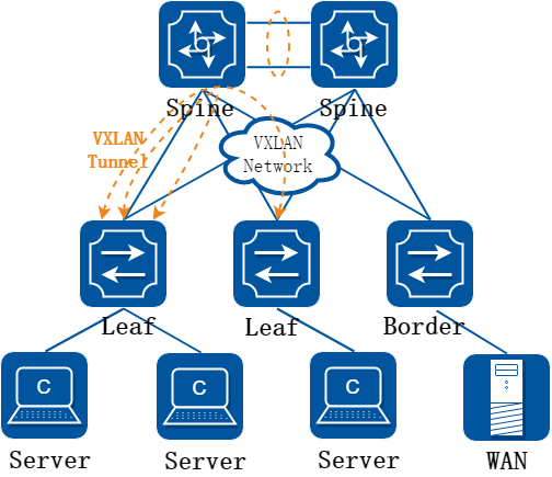
图17-52集中式网关示意图
集中式网关特点:
• 网关部署在Spine
• VTEP部署在Leaf
• 设备之间通过EVPN完成隧道建立和主机路由同步
• 有1台或多台专门接入外网的设备,我们把它叫做Border Leaf,Spine和Border通过默认路由互通
• 同一Leaf下的三层流量需绕行到Spine
• Spine需要保存整网的MAC和ARP
• 适合中小规模组网
优点:
• 接入设备(Leaf)不需要支持大容量的ARP表项
• 接入设备(Leaf)不需要支持基于VXLAN网络的三层转发表项查找功能,可以降低接入设备的成本。
缺点:
• 核心设备(spine)需要保留整网的ARP表项,组网规模受限
• 同一Leaf下的三层流量需绕行到Spine再转发,不是最优路径
2.集中式网关二层互访方案
VXLAN网络中的二层报文转发,存在以下两种方式:
• 单播:对于VXLAN网络中存在MAC表的报文,可以单播转发。
• BUM:非单播的报文通过头端复制表进行BUM(Broadcast, Unknown unicast, or Multicast)转发。
实现单播和BUM都需要先由控制面建立表项,下面将详细描述。
控制面建立二层BUM需要的表项: VXLAN网络中,BUM报文需要通过VXLAN隧道的头端复制列表进行转发。通过EVPN Type 3路由传递L2 VNI和L2 VTEP,同时会创建头端复制列表,流程如下。
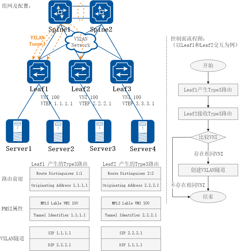
图17-53二层报文控制面创建隧道和头端复制表示意图
说明:
• Leaf1 产生Type 3 路由并发给远端
• Leaf2 收到远端VTEP邻居Type 3 路由后,发现与本地有相同的L2 VNI,建立一条到远端的VXLAN隧道,同时创建到远端的VXLAN隧道头端复制列表。
• Leaf1和Leaf3之间、Leaf2和Leaf3之间也重复以上过程,建立隧道和头端复制列表。
控制面建立二层单播需要的表项: 单个Leaf学习到Server的MAC地址后,通过EVPN将MAC表同步至所有Leaf,以实现二层已知单播转发。同步MAC地址依靠Type2路由。
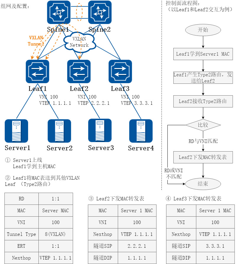
图17-54二层报文控制面MAC学习示意图
说明:
• Leaf1收集到本地主机 Server1的MAC 信息,封装一条EVPN的Type2路由,发送给邻居Leaf2;
• Leaf2接收到Type2路由后,对比本地的Route-target和EVPN实例对应的L2 VNI,如果相同,就将收到的MAC加到本地的MAC转发表中。
• Server1的MAC同样也会被Leaf3学习。
• Server2、Server3和Server4的MAC地址也重复以上步骤来学习,并同步到所有Leaf。
转发面二层互访流程
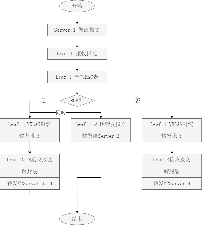
图17-55转发面流程图
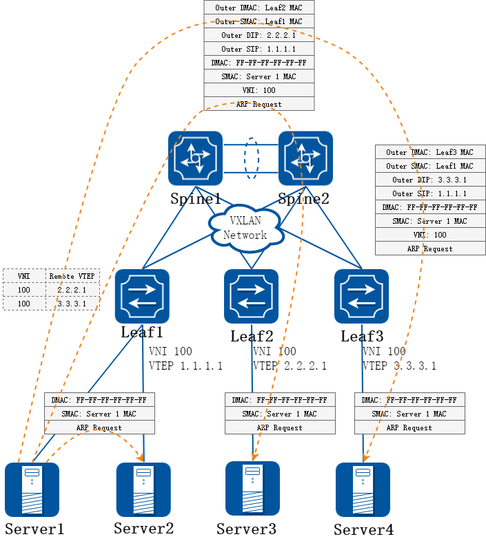
图17-56BUM
BUM说明:
• Leaf1收到来自主机Server1的报文,根据报文中接入的端口和VLAN信息获取对应的二层广播域,并判断报文的目的MAC是BUM MAC。
• Leaf1上VTEP根据对应的二层广播域获取对应VNI的头端复制隧道列表,依据获取的隧道列表进行报文复制,并进行VXLAN封装,并从出端口转发。
• Leaf2/Leaf3上VTEP收到VXLAN报文后,根据UDP目的端口号、源/目的IP地址、 VNI判断VXLAN报文的合法有效性。依据VNI获取对应的二层广播域,然后进行VXLAN解封装,获取内层二层报文。
• Leaf2/Leaf3根据获取的内层二层报文进行转发,如果二层报文的目的mac能够命中mac表,则根据mac表中查找到的端口进行报文封装和转发,否则将报文广播到Leaf的用户侧端口。
• 上述组网情况下,Server1和Server2之间的二层报文直接转发,不需要VXLAN封装。
注:VXLAN侧的BUM报文只能向用户侧广播,不能广播到VXLAN侧,否则会导致环路。
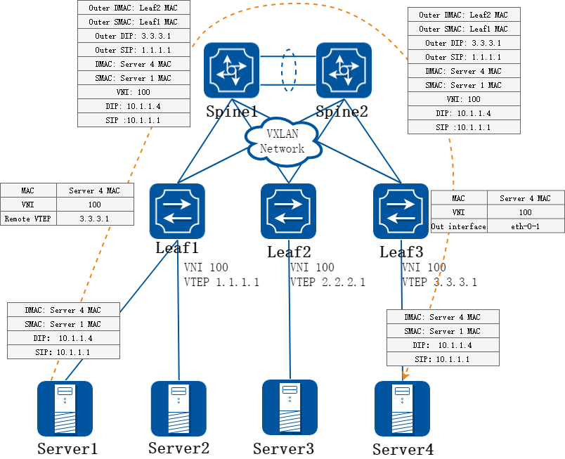
图17-57单播
单播说明:
• Leaf1收到来自主机Server的报文,根据报文中接入的端口和VLAN信息获取对应的二层广播域,并判断报文的目的MAC是已知单播MAC。
• Leaf1上VTEP根据查找到的VNI和远端VTEP地址进行VXLAN封装和报文转发。封装后的VXLAN报文通过Leaf1和Leaf3之间的IP网络进行转发。
• Leaf3上VTEP收到VXLAN报文后,根据UDP目的端口号、源/目的IP地址、 VNI判断VXLAN报文的合法有效性。依据VNI获取对应的二层广播域,然后进行VXLAN解封装,获取内层二层报文。
• Leaf3根据内层二层报文的目的MAC,查MAC表找到的出接口和封装信息,为报文添加VLAN Tag,转发给对应的终端Server 4。
3.集中式网关三层互访方案
在集中式网关环境中,三层转发查路由处理是在集中式网关节点上做的,Spine设备需要保存全部的三层表项,包括ARP表项和网段路由。 在下面拓扑中,Spine1和Spine2组成MLAG以保证可靠性。
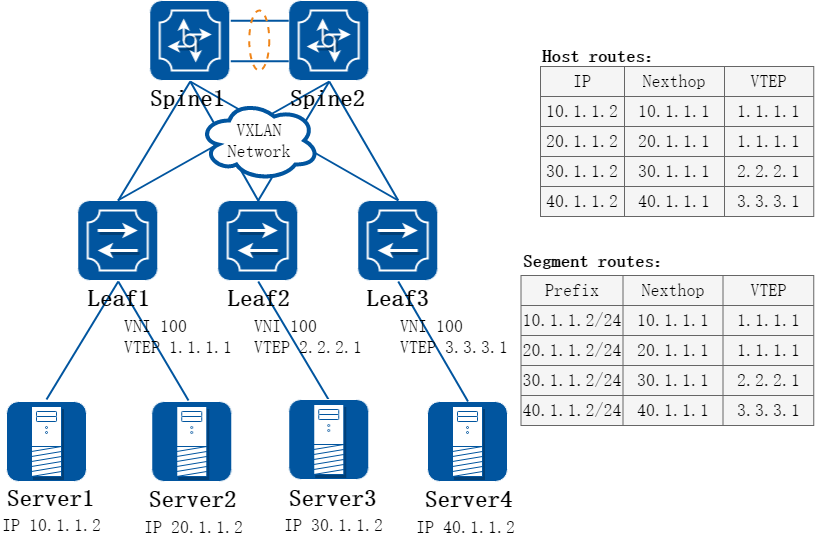
图17-58集中式网关三层组网
要实现三层转发,控制面需要学习主机路由(ARP)表项和网段路由表项。学习的过程如下文描述。
控制面学习ARP表项:
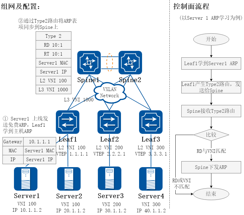
图17-59集中式网关ARP学习
控制面学习网段路由:
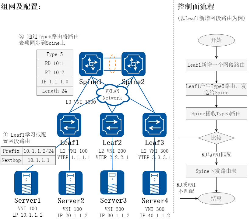
图17-60集中式网关网段路由学习
说明:
• 通过Type2路由将ARP同步到Spine上。
• 通过Type5路由将网段路由同步到Spine上。
• 在这个组网前提下,需要重复上图的步骤同步全部Server ARP和所有Leaf上的网段路由。
转发面三层互访流程
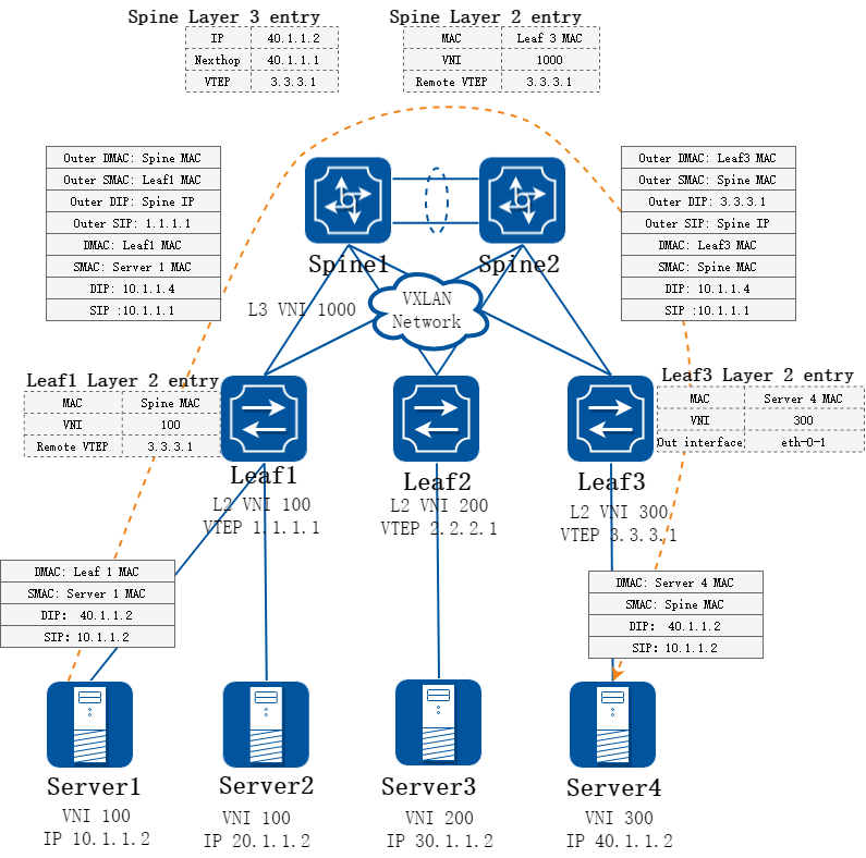
图17-61集中式网关三层报文转发组网
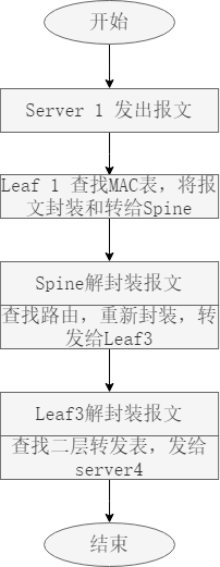
图17-62集中式网关三层报文转发流程图
说明: - 网关设备收到 VXLAN 报文后解封装,获取内层二层报文,判断二层报文目的 mac 为本机 mac,进入三层转发流程。根据内层报文的目的 IP 地址查路由表,进行三层转发。 - 根据路由表获取下一跳 IP 地址,根据 IP 地址查 ARP 表,如果 ARP 表出接口为 VXLAN隧道,则按照 ARP 表中的 VXLAN 隧道封装信息进行 VXLAN 封装,然后将报文发送出去。
分布式网关解决方案
1.分布式网关概述
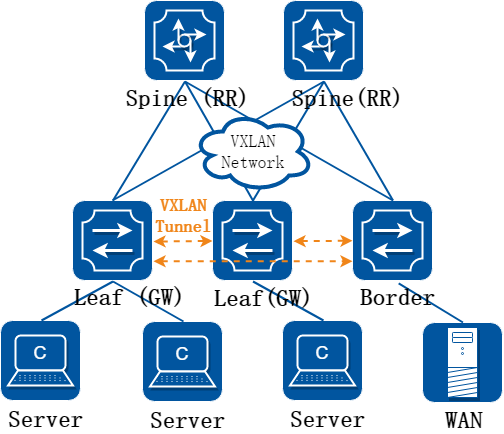
图17-63分布式网关示意图
分布式网关特点:
• 网关部署在Leaf,所有相同VXLAN的网关IP和MAC相同
• Leaf和Spine通过IP的ECMP互通
• Leaf节点同时承担VXLAN L2/3转发
• Leaf之间通过EVPN完成隧道建立和主机路由同步
• 同一Leaf下的三层流量无需绕行到Spine,所有流量的路径最优
• 本Leaf包含二层域所有端点的MAC和需要互通的三层域内所有端点的ARP(包括本地和远端)
• 适合中大规模组网
优点:
• 组网简单,广播域被限制在接入层以下
• Leaf和Spine之间通过运行路由协议,构建ECMP的三层可达的IP网络,可靠性高
• 同一Leaf下的三层流量无需绕行到Spine,所有流量的路径最优
缺点:
• 对接入设备(Leaf)性能规格要求更高。
Characteristic of distributed gateway:
• The gateway is deployed in Leaf, and the gateway IP address and MAC address of the same VXLAN are the same
• Leaf and Spine communicate with each other through IP ECMP
• The Leaf node also supports VXLAN L2/L3 forwarding
• EVPN is used to establish tunnels between leafs and synchronize routes between hosts
• The Layer 3 traffic in the same Leaf does not need to be routed to the spine. The path of all traffic is optimal.
• The Leaf contains the MAC of all endpoints in the Layer 2 domain and the ARP of all endpoints in the Layer 3 domain (including local and remote endpoints) that need to communicate with each other
• Suitable for medium and large scale networking
Advantage:
• The network is simple, and the broadcast domain is restricted below the access layer
• By running routing protocols between Leaf and spine, a layer 3 reachable IP network of ECMP is constructed and the reliability is high
• The Layer-3 traffic in Leaf does not need to sned to spine, and all traffic paths are optimal
Shortcoming:
• Higher performance specifications for access devices (Leaf).
2.分布式网关二层互访方案
分布式网关下二层互访与集中式网关的处理相同。
3.分布式网关三层互访方案
分布式网关通过EVPN在各个Leaf之间同步三层路由信息。Spine扮演路由反射器(RR)的角色。 要实现三层转发,各Leaf需要学习主机路由(ARP)表项和网段路由表项。学习的过程如下文描述。
控制面学习ARP表项:
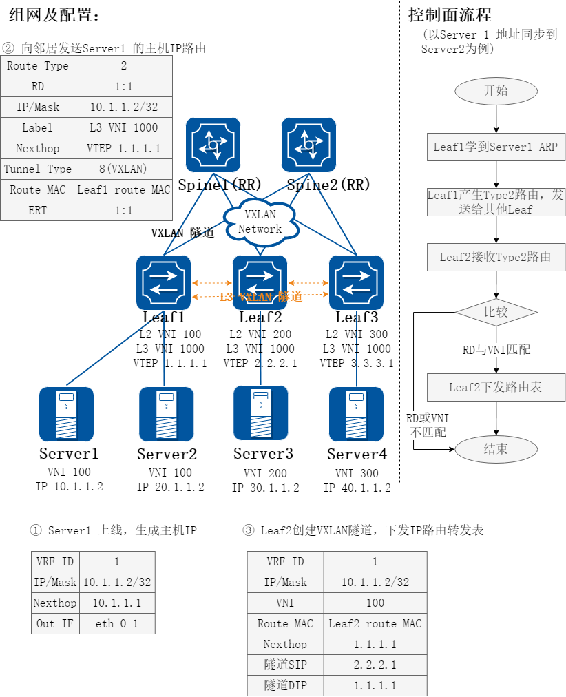
图17-64分布式网关ARP学习
控制面学习网段路由:
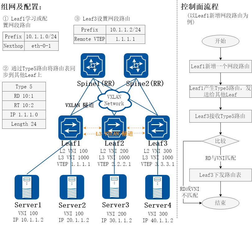
图17-65分布式网关网段路由学习
控制面流程说明:
• 主机上线后,Leaf 学习到主机 IP 路由,把该主机 IP 路由通过 EVPN 发送给其他邻居,需要携带对应租户的 L3 VNI, 下一跳修改为本地 VTEP 地址;
• 远端 Leaf 学习到主机 IP 路由后,下发到对应的 VPN 实例,接着根据下一跳去触发创建动态的 L3 VXLAN 隧道, 并把路由关联上该隧道,下发 IP路由转发表。
• 上述示意图中每个Server的ARP都需要学习,并同步到整个VXLAN网络的每个Leaf上。
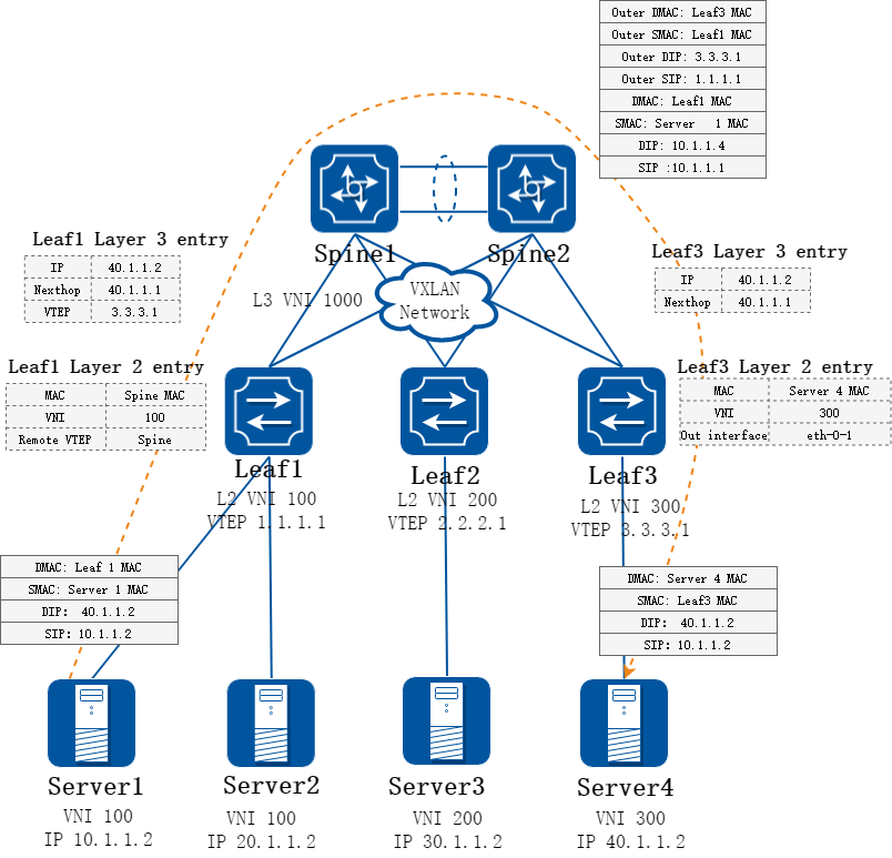
图17-66分布式网关三层报文转发
转发面流程说明:
• Leaf1收到Server1发过来的报文, 检测报文的目的MAC是网关MAC,即是自己Leaf的MAC,则要走三层查路由转发, 通过报文入接口找到对应的VPN实例。
• 在找到的VPN实例中,根据报文的目的IP查找路由表,封装VXLAN报文:带上L3 VNI、RouterMac等,送给Leaf3。
• Leaf3上收到VXLAN报文后,判断DMAC是否为自己的,发现该Mac是自己的系统Mac,所以要走三层转发,通过VNI找到对应的VPN实例,在该VPN实例中查找路由表,发现该路由下一跳是网关接口,封装报文送给Server4。
虚拟机迁移解决方案
虚拟机迁移,是指虚拟机从一个Leaf节点迁移到另一个Leaf节点下。这种情况下一般需要保持虚拟机原有的MAC和IP不变,因而VXLAN网络中的MAC和ARP、路由等表项都需要及时更新。
虚拟机迁移后,一般都会发送免费ARP 报文,依靠免费ARP报文,可以使主机路由、ARP等信息得到刷新。
迁移过程需要依赖EVPN控制面通告通告主机ARP, 并且ARP中需要携带迁移属性,这里通过BGP update消息中的Mac mobility 扩展团体属性来通告。每次迁移都需要将携带的Mac mobility的SeqNum加 1。
Mac mobility 扩展团体报文格式如下。
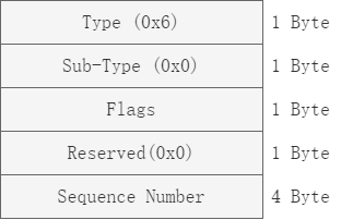
图17-67虚拟机迁移示意图
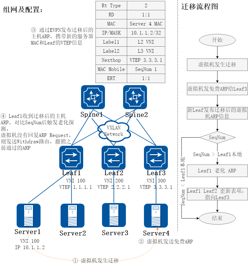
图17-68Mac mobility扩展团体属性
说明:
• 虚拟机10.1.1.2原先在Server1位置,虚拟机的ARP、主机路由均已学到,并已同步到所有Leaf上。
• 因为业务部属需要,虚拟机10.1.1.2从Server1位置迁移到Server4位置。
• 迁移后的虚拟机开机上线,Leaf3 会收到来自虚拟机的免费ARP。
• Leaf3发现这个ARP原来是Leaf1发给自己的,刷新本地表项的同时,封装ARP更新信息,发给其他邻居。
• Leaf1收到来自Leaf3的报文,发现这个ARP原来是自己这里的虚拟机,需要对比Mac mobility的SeqNum。如果SeqNum大于本地最后一次消息中的SeqNum值,才认为这个更新是有效的,否则不处理。
• 当收到的SeqNum大于之前最后一次SeqNum值时,Leaf1需要迅速老化之前的ARP,Leaf1使用ARP request报文去探测迁移前的虚拟机,一旦ARP request超时未回,Leaf1 会发送withdraw 路由,通告之前的ARP、主机路由都作废。
• Leaf2和Leaf3收到Leaf1发来的撤销消息,删除旧有表项;Leaf1和Leaf2收到Leaf3发来的更新消息,新增本地表项。
主机双活可靠性解决方案
图17-69主机双活可靠性示意图
主机接入可靠性,可以通过MLAG接入Leaf;Leaf上通过跨设备的LAG与主机对接, 通过配置相同的IP作为VTEP, 与其他设备建立隧道,MLAG 的设备间部署互联链路,用作故障情况下路径保护。
正常情况下,设备从某个双归接口接收到流量,本设备直接转发给其他服务器或封装隧道发给其他设备;设备接收到隧道封装的流量,剥离封装本地转发给主机;
在双归接口故障后,从主机或隧道接收的流量经过双归设备间的互联链路转发到与主机互联的另一链路。
运行 BGP EVPN 后对外通告本地主机路由时,发布相同的 VTEP IP、 RouterMAC。