


5.1.1概述
简介
静态路由是一种特殊的路由,由管理员手工配置。当网络结构比较简单时,只需配置静态路由就可以使网络正常工作。合理设置和使用静态路由可以改进网络性能,并可为重要的网络应用保证带宽。静态路由的缺点在于:当网络发生故障或者拓扑发生变化后,可能会出现路由不可达,从而导致网络中断。此时必须由网络管理员手工修改静态路由的配置。
静态路由在小型网络中非常有用,提供使几个目的地可达的简单解决方案。大型网络建议使用动态路由协议。
静态路由是由网络前缀(主机地址)和下一跳(网关)组成。
5.1.2配置举例
1.组网拓扑
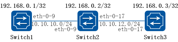
图5-1ip unicast routing
这个例子说明在一个简单的网络拓扑结构下如何使能静态路由。
路由器Switch1配置三个静态路由,一个是远程网络10.10.12.0/24,另外两个是到路由器Switch2和Switch3的环回地址(主机地址)。路由器Switch3配置了一条默认静态路由,相当于单独的静态路由配置使用相同的网关或下一跳地址。路由器Switch2有两条路由,每一条路由的目的地都是远端路由器的环回口地址。
2.配置步骤
步骤 1进入配置模式
Switch# configure terminal
步骤 2进入接口配置模式,配置接口属性和ip地址
在Switch1配置:
Switch1(config)# interface eth-0-9
Switch1(config-if)# no shutdown
Switch1(config-if)# no switchport
Switch1(config-if)# ip address 10.10.10.1/24
Switch1(config-if)# exit
Switch1(config)# interface loopback 0
Switch1(config-if)# ip address 192.168.0.1/32
Switch1(config-if)# exit
在Switch2配置:
Switch2(config)# interface eth-0-9
Switch2(config-if)# no shutdown
Switch2(config-if)# no switchport
Switch2(config-if)# ip address 10.10.10.2/24
Switch2(config-if)# exit
Switch2(config)# interface eth-0-17
Switch2(config-if)# no shutdown
Switch2(config-if)# no switchport
Switch2(config-if)# ip address 10.10.12.2/24
Switch2(config-if)# exit
Switch2(config)# interface loopback 0
Switch2(config-if)# ip address 192.168.0.2/32
Switch2(config-if)# exit
在Switch3配置:
Switch3(config)# interface eth-0-17
Switch3(config-if)# no shutdown
Switch3(config-if)# no switchport
Switch3(config-if)# ip address 10.10.12.3/24
Switch3(config-if)# exit
Switch3(config)# interface loopback 0
Switch3(config-if)# ip add 192.168.0.3/32
Switch3(config-if)# exit
步骤 3配置静态路由
在Switch1配置:
说明:指定目的前缀和掩码网关所需网络,例如,10.10.12.0/24,为他们每个添加网关(对此所有情况下为 10.10.10.2)。由于Switch2是唯一可用的下一跳,可以配置默认路由而不是配置为单独的地址
Switch1(config)# ip route 10.10.12.0/24 10.10.10.2
Switch1(config)# ip route 192.168.0.2/32 10.10.10.2
Switch1(config)# ip route 192.168.0.3/32 10.10.10.2
在Switch2配置:
Switch2(config)# ip route 192.168.0.1/32 10.10.10.1
Switch2(config)# ip route 192.168.0.3/32 10.10.12.3
在Switch3配置:
说明:指定10.10.12.2作为到达任意网络的默认网关,因为10.10.12.2是唯一的一条可以指定默认网关,而不是单个网络或主机的网关指定。
Switch3(config)# ip route 0.0.0.0/0 10.10.12.2
步骤 4退出配置模式
Switch(config)# end
步骤 5检查配置
使用下列命令,查看Switch1上的路由:
Switch1# show ip route
Codes: K - kernel, C - connected, S - static, R - RIP, B - BGP
O - OSPF, IA - OSPF inter area
N1 - OSPF NSSA external type 1, N2 - OSPF NSSA external type 2
E1 - OSPF external type 1, E2 - OSPF external type 2
i - IS-IS, L1 - IS-IS level-1, L2 - IS-IS level-2, ia - IS-IS inter area
[*] - [AD/Metric]
* - candidate default
C 10.10.10.0/24 is directly connected, eth-0-9
C 10.10.10.1/32 is in local loopback, eth-0-9
S 10.10.12.0/24 [1/0] via 10.10.10.2, eth-0-9
C 192.168.0.1/32 is directly connected, loopback0
S 192.168.0.2/32 [1/0] via 10.10.10.2, eth-0-9
S 192.168.0.3/32 [1/0] via 10.10.10.2, eth-0-9
使用下列命令,查看Switch2上的路由:
Switch2# show ip route
Codes: K - kernel, C - connected, S - static, R - RIP, B - BGP
O - OSPF, IA - OSPF inter area
N1 - OSPF NSSA external type 1, N2 - OSPF NSSA external type 2
E1 - OSPF external type 1, E2 - OSPF external type 2
i - IS-IS, L1 - IS-IS level-1, L2 - IS-IS level-2, ia - IS-IS inter area
[*] - [AD/Metric]
* - candidate default
C 10.10.10.0/24 is directly connected, eth-0-9
C 10.10.10.2/32 is in local loopback, eth-0-9
C 10.10.12.0/24 is directly connected, eth-0-17
C 10.10.12.2/32 is in local loopback, eth-0-17
S 192.168.0.1/32 [1/0] via 10.10.10.1, eth-0-9
C 192.168.0.2/32 is directly connected, loopback0
S 192.168.0.3/32 [1/0] via 10.10.12.3, eth-0-17
使用下列命令,查看Switch3上的路由:
Switch3# show ip route
Codes: K - kernel, C - connected, S - static, R - RIP, B - BGP
O - OSPF, IA - OSPF inter area
N1 - OSPF NSSA external type 1, N2 - OSPF NSSA external type 2
E1 - OSPF external type 1, E2 - OSPF external type 2
i - IS-IS, L1 - IS-IS level-1, L2 - IS-IS level-2, ia - IS-IS inter area
[*] - [AD/Metric]
* - candidate default
Gateway of last resort is 10.10.12.2 to network 0.0.0.0
S* 0.0.0.0/0 [1/0] via 10.10.12.2, eth-0-17
C 10.10.12.0/24 is directly connected, eth-0-17
C 10.10.12.3/32 is in local loopback, eth-0-17
C 192.168.0.3/32 is directly connected, loopback0
5.2.1概述
简介
RIP(Routing Information Protocol,路由信息协议)是一种较为简单的内部网关协议(Interior Gateway Protocol,IGP),主要用于规模较小的网络中。
RIP是一种基于距离矢量(Distance-Vector)算法的协议,它通过UDP报文进行路由信息的交换。RIP 使用跳数(Hop Count)来衡量到达目的地址的距离,称为路由权(RoutingCost)。在RIP中,路由器到与它直接相连网络的跳数为0,通过一个路由器可达的网络的跳数为1,其余依此类推。为限制收敛时间,RIP规定cost的取值为0~15之间的整数,cost取值大于或等于16的跳数被定义为无穷大,即目的网络或主机不可达。
为提高性能,防止产生路由环,RIP支持水平分割(Split Horizon)。RIP还可引入其它路由协议所得到的路由。
原理描述
参考 2453
5.2.2配置举例
配置启用rip
1.组网拓扑
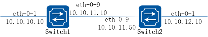
图5-2enable rip
2.配置步骤
步骤 1进入配置模式
Switch# configure terminal
步骤 2进入接口配置模式,配置接口属性和ip地址
在Switch1配置:
Switch1(config)# interface eth-0-1
Switch1(config-if)# no switchport
Switch1(config-if)# no shutdown
Switch1(config-if)# ip address 10.10.10.10/24
Switch1(config-if)# exit
Switch1(config)# interface eth-0-9
Switch1(config-if)# no switchport
Switch1(config-if)# no shutdown
Switch1(config-if)# ip address 10.10.11.10/24
Switch1(config-if)# exit
在Switch2配置:
Switch2(config)# interface eth-0-1
Switch2(config-if)# no switchport
Switch2(config-if)# no shutdown
Switch2(config-if)# ip address 10.10.12.10/24
Switch2(config-if)# exit
Switch2(config)# interface eth-0-9
Switch2(config-if)# no switchport
Switch2(config-if)# no shutdown
Switch2(config-if)# ip address 10.10.11.50/24
Switch2(config-if)# exit
步骤 3启用rip路由,发布需要的网段
在Switch1配置:
Switch1(config)# router rip
Switch1(config-router)#network 10.10.10.0/24
Switch1(config-router)#network 10.10.11.0/24
Switch1(config-router)# exit
在Switch2配置:
Switch2(config)# router rip
Switch2(config-router)#network 10.10.11.0/24
Switch2(config-router)#network 10.10.12.0/24
Switch2(config-router)# exit
步骤 4退出配置模式
Switch(config)# end
步骤 5检查配置
使用下列命令查看Switch1 rip数据库:
Switch1# show ip rip database
Codes: R - RIP, Rc - RIP connected, Rs - RIP static, K - Kernel,
C - Connected, S - Static, O - OSPF, I - IS-IS, B - BGP
Network Next Hop Metric From If Time
Rc 10.10.10.0/24 1 eth-0-1
Rc 10.10.11.0/24 1 eth-0-9
R 10.10.12.0/24 10.10.11.50 2 10.10.11.50 eth-0-9 00:02:52
使用下列命令查看Switch1 rip协议运行状态:
Switch1# show ip protocols rip
Routing protocol is "rip"
Sending updates every 30 seconds with +/-5 seconds, next due in 17 seconds
Timeout after 180 seconds, Garbage collect after 120 seconds
Outgoing update filter list for all interface is not set
Incoming update filter list for all interface is not set
Default redistribution metric is 1
Redistributing:
Default version control: send version 2, receive version 2
Interface Send Recv Key-chain
eth-0-1 2 2
eth-0-9 2 2
Routing for Networks:
10.10.10.0/24
10.10.11.0/24
Routing Information Sources:
Gateway Distance Last Update Bad Packets Bad Routes
10.10.11.50 120 00:00:22 0 0
Number of routes (including connected): 3
Distance: (default is 120)
使用下列命令查看Switch1 rip端口状态:
Switch1# show ip rip interface
eth-0-1 is up, line protocol is up
Routing Protocol: RIP
Receive RIP packets
Send RIP packets
Passive interface: Disabled
Split horizon: Enabled with Poisoned Reversed
IP interface address:
10.10.10.10/24
eth-0-9 is up, line protocol is up
Routing Protocol: RIP
Receive RIP packets
Send RIP packets
Passive interface: Disabled
Split horizon: Enabled with Poisoned Reversed
IP interface address:
10.10.11.10/24
使用下列命令查看Switch1上的路由:
Switch1# show ip route
Codes: K - kernel, C - connected, S - static, R - RIP, B - BGP
O - OSPF, IA - OSPF inter area
N1 - OSPF NSSA external type 1, N2 - OSPF NSSA external type 2
E1 - OSPF external type 1, E2 - OSPF external type 2
i - IS-IS, L1 - IS-IS level-1, L2 - IS-IS level-2, ia - IS-IS inter area
[*] - [AD/Metric]
* - candidate default
C 10.10.10.0/24 is directly connected, eth-0-1
C 10.10.10.10/32 is in local loopback, eth-0-1
C 10.10.11.0/24 is directly connected, eth-0-9
C 10.10.11.10/32 is in local loopback, eth-0-9
R 10.10.12.0/24 [120/2] via 10.10.11.50, eth-0-9, 00:25:50
配置rip版本
1.组网拓扑
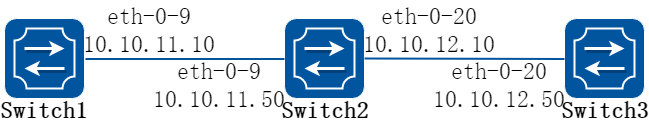
图5-3rip version
配置路由接口发送接收的RIP版本。在下面例子中Switch2 在eth-0-9和eth-0-20上面发送和接收的RIP版本是v1和v2。
2.配置步骤
步骤 1进入配置模式
以下配置在Switch2进行:
Switch2# configure terminal
步骤 2启用路由协议
Switch2(config)# router rip
Switch2(config-router)# exit
步骤 3进入接口配置模式,配置接口rip版本信息
Switch2(config)# interface eth-0-9
Switch2(config-if)# ip rip send version 1 2
Switch2(config-if)# ip rip receive version 1 2
Switch2(config-if)# quit
Switch2(config)# interface eth-0-20
Switch2(config-if)# ip rip send version 1 2
Switch2(config-if)# ip rip receive version 1 2
Switch2(config-if)# quit
步骤 4退出配置模式
Switch2(config)# end
步骤 5检查配置
使用下列命令,查看Switch1配置:
Switch1# show running-config
interface eth-0-9
no switchport
ip address 10.10.11.10/24
!
router rip
network 10.10.11.0/24
使用下列命令,查看Switch2的rip数据库信息:
Switch2# show ip rip database
Codes: R - RIP, Rc - RIP connected, Rs - RIP static, K - Kernel,
C - Connected, S - Static, O - OSPF, I - IS-IS, B - BGP
Network Next Hop Metric From If Time
R 10.0.0.0/8 1 eth-0-9
Rc 10.10.11.0/24 1 eth-0-9
Rc 10.10.12.0/24 1 eth-0-20
使用下列命令,查看Switch2的rip协议运行状态信息:
Switch2# show ip protocols rip
Routing protocol is "rip"
Sending updates every 30 seconds with +/-5 seconds, next due in 1 seconds
Timeout after 180 seconds, Garbage collect after 120 seconds
Outgoing update filter list for all interface is not set
Incoming update filter list for all interface is not set
Default redistribution metric is 1
Redistributing:
Default version control: send version 2, receive version 2
Interface Send Recv Key-chain
eth-0-9 1 2 1 2
eth-0-20 1 2 1 2
Routing for Networks:
10.10.11.0/24
10.10.12.0/24
Routing Information Sources:
Gateway Distance Last Update Bad Packets Bad Routes
10.10.11.10 120 00:00:22 0 0
10.10.12.50 120 00:00:27 0 0
Number of routes (including connected): 3
Distance: (default is 120)
使用下列命令,查看Switch2的使用下列命令查看rip端口状态:
Switch2# show ip rip interface
eth-0-9 is up, line protocol is up
Routing Protocol: RIP
Receive RIPv1 and RIPv2 packets
Send RIPv1 and RIPv2 packets
Passive interface: Disabled
Split horizon: Enabled with Poisoned Reversed
IP interface address:
10.10.11.50/24
eth-0-20 is up, line protocol is up
Routing Protocol: RIP
Receive RIPv1 and RIPv2 packets
Send RIPv1 and RIPv2 packets
Passive interface: Disabled
Split horizon: Enabled with Poisoned Reversed
IP interface address:
10.10.12.10/24
使用下列命令,查看Switch2的配置:
Switch2# show run
interface eth-0-9
no switchport
ip address 10.10.11.50/24
ip rip send version 1 2
ip rip receive version 1 2
!
interface eth-0-20
no switchport
ip address 10.10.12.10/24
ip rip send version 1 2
ip rip receive version 1 2
!
router rip
network 10.10.11.0/24
network 10.10.12.0/24
使用下列命令,查看Switch3配置:
Switch3# show running-config
interface eth-0-20
no switchport
ip address 10.10.12.50/24
!
router rip
network 10.10.12.0/24
配置Metric参数
1.组网拓扑
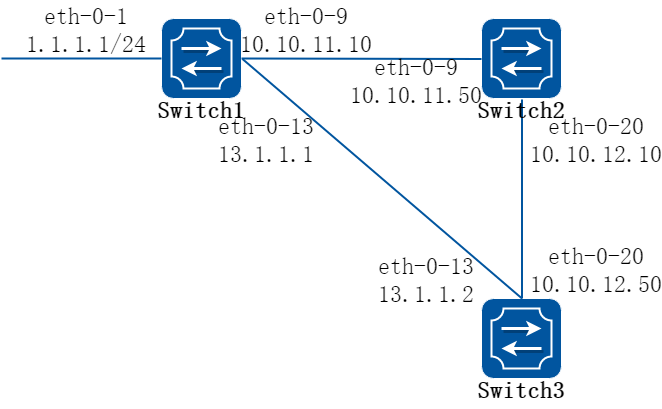
图5-4rip metric
附加度量值是附加在RIP路由上的输入输出度量值,包括发送附加度量值和接收附加度量值。发送附加度量值不会改变路由表中的路由度量值,仅当接口发送RIP路由信息时才会添加到发送路由上;接收附加度量值会影响接收到的路由度量值,接口接收到一条合法的RIP 路由时,在将其加入路由表前会把度量值附加到该路由上。附加度量值一般包括如下的参数:
• 指定增加路由Metric的ACL,参数说明如下:
• In:应用在从邻居路由器学习到的RIP的路由上
• Out:应用在发布给邻居路由器RIP通告上
• 匹配ACL路由的偏移值Metric
• 应用偏移列表的接口
如果有一个路由匹配全局偏移表(不指定接口)和一个基于接口的偏移列表,此时基于接口的偏移列表优先。在这种情况下,基于接口的偏移列表的度量值是被加到路由上。
下面例子讲述如何在Switch1上将1.1.1.0在eth-0-13接口上增加metric 3。
2.配置步骤
步骤 1环境准备, 检查已有配置
Switch1
interface eth-0-1
no switchport
ip address 1.1.1.1/24
!
interface eth-0-9
no switchport
ip address 10.10.11.10/24
!
interface eth-0-13
no switchport
ip address 13.1.1.1/24
!
router rip
network 1.1.1.0/24
network 10.10.11.0/24
network 13.1.1.0/24
Switch2
interface eth-0-9
no switchport
ip address 10.10.11.50/24
!
interface eth-0-20
no switchport
ip address 10.10.12.10/24
!
router rip
network 10.10.11.0/24
network 10.10.12.0/24
Switch3
interface eth-0-13
no switchport
ip address 13.1.1.2/24
!
interface eth-0-20
no switchport
ip address 10.10.12.50/24
!
router rip
network 10.10.12.0/24
network 13.1.1.0/24
Switch3上已学到rip路由,显示如下:
Switch# show ip route rip
R 1.1.1.0/24 [120/2] via 13.1.1.1, eth-0-13, 00:07:46
R 10.10.11.0/24 [120/2] via 13.1.1.1, eth-0-13, 00:07:39
[120/2] via 10.10.12.10, eth-0-20, 00:07:39
Change router 1.1.1.0/24 via 10.10.12.10
步骤 2进入配置模式
以下配置在Switch1进行:
Switch1# configure terminal
步骤 3配置ACL
Switch1(config)#ip access-list ripoffset
Switch1(config-ip-acl)#permit any 1.1.1.0 0.0.0.255 any
步骤 4启用rip路由,设置偏移列表的Metric值
Switch1(config-ip-acl)# router rip
Switch1(config-router)# offset-list ripoffset out 3 eth-0-13
步骤 5退出配置模式
Switch1(config-router)# end
步骤 6检查配置
Switch3上学到rip路由,其中Switch1发布的路由metric变为3,显示如下:
Switch3# show ip route rip
R 1.1.1.0/24 [120/3] via 10.10.12.10, eth-0-20, 00:00:02
R 10.10.11.0/24 [120/2] via 13.1.1.1, eth-0-13, 00:11:40
[120/2] via 10.10.12.10, eth-0-20, 00:11:40
配置管理距离
1.组网拓扑
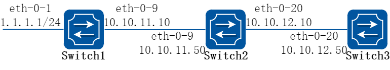
图5-5rip distance
默认情况下,RIP的管理距离是120。比较路由时,管理距离越低,路由越容易被选中。
下面例子讲述了如何修改RIP的管理距离,通过以下步骤改变Switch3上的1.1.1.0网段的RIP管理距离。
2.配置步骤
步骤 1环境准备, 检查已有配置
Switch1
interface eth-0-1
no switchport
ip address 1.1.1.1/24
!
interface eth-0-9
no switchport
ip address 10.10.11.10/24
!
router ospf
network 1.1.1.0/24 area 0
network 10.10.11.0/24 area 0
!
router rip
network 1.1.1.0/24
network 10.10.11.0/24
Switch2
interface eth-0-9
no switchport
ip address 10.10.11.50/24
!
interface eth-0-20
no switchport
ip address 10.10.12.10/24
!
router ospf
network 10.10.11.0/24 area 0
network 10.10.12.0/24 area 0
!
router rip
network 10.10.11.0/24
network 10.10.12.0/24
Switch3
interface eth-0-20
no switchport
ip address 10.10.12.50/24
!
router ospf
network 10.10.12.0/24 area 0
!
router rip
network 10.10.12.0/24
Switch3上已学到的路由,显示如下:
Switch3# show ip route
Codes: K - kernel, C - connected, S - static, R - RIP, B - BGP
O - OSPF, IA - OSPF inter area
N1 - OSPF NSSA external type 1, N2 - OSPF NSSA external type 2
E1 - OSPF external type 1, E2 - OSPF external type 2
i - IS-IS, L1 - IS-IS level-1, L2 - IS-IS level-2, ia - IS-IS inter area
[*] - [AD/Metric]
* - candidate default
O 1.1.1.0/24 [110/3] via 10.10.12.10, eth-0-20, 01:05:49
O 10.10.11.0/24 [110/2] via 10.10.12.10, eth-0-20, 01:05:49
C 10.10.12.0/24 is directly connected, eth-0-20
C 10.10.12.50/32 is in local loopback, eth-0-20
步骤 2进入配置模式
以下配置在Switch3进行:
Switch3# configure terminal
步骤 3配置ACL
Switch3(config)#ip access-list ripdistancelist
Switch3(config-ip-acl)#permit any 1.1.1.0 0.0.0.255 any
步骤 4启用rip路由,设置RIP路由的管理距离
Switch3(config-ip-acl)# router rip
Switch3(config-router)# distance 100 0.0.0.0/0 ripdistancelist
步骤 5退出配置模式
Switch3(config-router)# end
步骤 6检查配置
Switch3上学到rip路由,其中rip路由管理距离变为100,显示如下:
Switch3# show ip route
Codes: K - kernel, C - connected, S - static, R - RIP, B - BGP
O - OSPF, IA - OSPF inter area
N1 - OSPF NSSA external type 1, N2 - OSPF NSSA external type 2
E1 - OSPF external type 1, E2 - OSPF external type 2
i - IS-IS, L1 - IS-IS level-1, L2 - IS-IS level-2, ia - IS-IS inter area
[*] - [AD/Metric]
* - candidate default
R 1.1.1.0/24 [100/3] via 10.10.12.10, eth-0-20, 00:00:02
O 10.10.11.0/24 [110/2] via 10.10.12.10, eth-0-20, 01:10:42
C 10.10.12.0/24 is directly connected, eth-0-20
C 10.10.12.50/32 is in local loopback, eth-0-20
配置重发布
1.组网拓扑
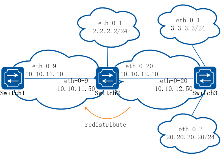
图5-6rip redistribute
用户可以将静态路由,直连路由以及其他路由协议比如OSPF的路由重分布到RIP中并被RIP发送给它的邻居。
默认RIP的重发布Metric为1,最大16。
将特定的路由重发布到RIP上,其度量值可以是默认的,也可以是修改后的。 下面例子讲述如何重分布其他的路由信息到RIP。
2.配置步骤
步骤 1环境准备, 检查已有配置
Switch1
interface eth-0-9
no switchport
ip address 10.10.11.10/24
!
router rip
network 10.10.11.0/24
Switch2
interface eth-0-1
no switchport
ip address 2.2.2.2/24
!
interface eth-0-9
no switchport
ip address 10.10.11.50/24
!
interface eth-0-20
no switchport
ip address 10.10.12.10/24
!
router ospf
network 10.10.12.0/24 area 0
!
router rip
network 10.10.11.0/24
!
ip route 20.20.20.0/24 10.10.12.50
Switch3
interface eth-0-1
no switchport
ip address 3.3.3.3/24
!
interface eth-0-2
no switchport
ip address 20.20.20.20/24
!
interface eth-0-20
no switchport
ip address 10.10.12.50/24
!
router ospf
network 3.3.3.0/24 area 0
network 10.10.12.0/24 area 0
Switch1上已学到的路由,显示如下:
Switch1# show ip route
Codes: K - kernel, C - connected, S - static, R - RIP, B - BGP
O - OSPF, IA - OSPF inter area
N1 - OSPF NSSA external type 1, N2 - OSPF NSSA external type 2
E1 - OSPF external type 1, E2 - OSPF external type 2
i - IS-IS, L1 - IS-IS level-1, L2 - IS-IS level-2, ia - IS-IS inter area
[*] - [AD/Metric]
* - candidate default
C 10.10.11.0/24 is directly connected, eth-0-9
C 10.10.11.10/32 is in local loopback, eth-0-9
Switch2上已学到的路由,显示如下:
Switch2# show ip route
Codes: K - kernel, C - connected, S - static, R - RIP, B - BGP
O - OSPF, IA - OSPF inter area
N1 - OSPF NSSA external type 1, N2 - OSPF NSSA external type 2
E1 - OSPF external type 1, E2 - OSPF external type 2
i - IS-IS, L1 - IS-IS level-1, L2 - IS-IS level-2, ia - IS-IS inter area
[*] - [AD/Metric]
* - candidate default
C 2.2.2.0/24 is directly connected, eth-0-1
C 2.2.2.02/32 is in local loopback, eth-0-1
O 3.3.3.0/24 [110/2] via 10.10.12.50, eth-0-20, 01:05:41
C 10.10.11.0/24 is directly connected, eth-0-9
C 10.10.11.50/32 is in local loopback, eth-0-9
C 10.10.12.0/24 is directly connected, eth-0-20
C 10.10.12.10/24 is in local loopback, eth-0-20
S 20.20.20.0/24 [1/0] via 10.10.12.50, eth-0-20
步骤 2进入配置模式
以下配置在Switch2进行:
Switch2# configure terminal
步骤 3启用rip路由,设置metric,设置需要重发布的路由类型
Switch2(config)# router rip
Switch2(config-router)# default-metric 2
Switch2(config-router)# redistribute static
Switch2(config-router)# redistribute connected
Switch2(config-router)# redistribute ospf metric 5
ospf重发布直连路由(可选):
Switch2(config)# router ospf
Switch2(config-router)# redistribute connected
步骤 4退出配置模式
Switch2(config-router)# end
步骤 5检查配置
Switch1上学到的路由,显示如下:
Switch1# show ip route
Codes: K - kernel, C - connected, S - static, R - RIP, B - BGP
O - OSPF, IA - OSPF inter area
N1 - OSPF NSSA external type 1, N2 - OSPF NSSA external type 2
E1 - OSPF external type 1, E2 - OSPF external type 2
i - IS-IS, L1 - IS-IS level-1, L2 - IS-IS level-2, ia - IS-IS inter area
[*] - [AD/Metric]
* - candidate default
R 2.2.2.0/24 [120/3] via 10.10.11.50, eth-0-9, 00:02:36
R 3.3.3.0/24 [120/6] via 10.10.11.50, eth-0-9, 00:02:26
C 10.10.11.0/24 is directly connected, eth-0-9
C 10.10.11.10/32 is in local loopback eth-0-9
R 10.10.12.0/24 [120/3] via 10.10.11.50, eth-0-9, 00:02:36
R 20.20.20.0/24 [120/3] via 10.10.11.50, eth-0-9, 00:02:41
配置水平分割参数
1.组网拓扑
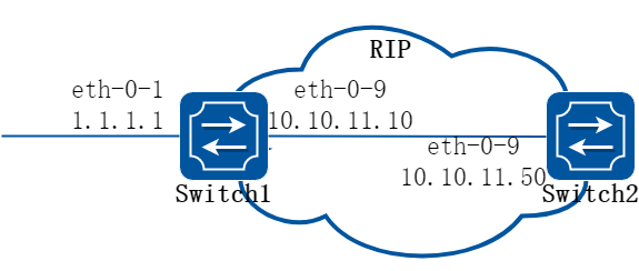
图5-7rip split-horizon
通常情况下,连接到广播网络并且使用距离矢量路由协议的路由器,使用水平分割机制来避免环路。配置水平分割可以使得从一个接口学到的路由不能通过此接口向外发布,这通常优化了多个路由器之间的通信,尤其在链路中断时。
配置毒性逆转可以使得从一个接口学到的路由还可以从这个接口向外发布,但这些路由的度量值已设置为16,即不可达。
2.配置步骤
步骤 1环境准备, 检查已有配置
Switch1
interface eth-0-1
no switchport
ip address 1.1.1.1/24
!
interface eth-0-9
no switchport
ip address 10.10.11.10/24
!
router rip
network 10.10.11.0/24
redistribute connected
Switch2
interface eth-0-9
no switchport
ip address 10.10.11.50/24
!
router rip
network 10.10.11.0/24
步骤 2在Switch2打开debug 开关(可选)
Switch# debug rip packet send detail
Switch# terminal monitor
步骤 3进入配置模式
以下配置在Switch2进行:
Switch2# configure terminal
步骤 4进入接口配置模式,设置水平分割
禁用水平分割:
Switch2(config)#interface eth-0-9
Switch2(config-if)# no ip rip split-horizon
当debug开关打开时,有如下信息显示:
Apr 8 06:24:25 Switch RIP4-7: SEND[eth-0-9]: Send to 224.0.0.9:520
Apr 8 06:24:25 Switch RIP4-7: SEND[eth-0-9]: RESPONSE version 2 packet size 44
Apr 8 06:24:25 Switch RIP4-7: 1.1.1.0/24 -> 0.0.0.0 family 2 tag 0 metric 2
Apr 8 06:24:25 Switch RIP4-7: 10.10.11.0/24 -> 0.0.0.0 family 2 tag 0 metric 1
启用水平分割和毒性逆转:
Switch2(config-if)# ip rip split-horizon
Switch2(config-if)# ip rip split-horizon poisoned
当debug开关打开时,有如下提示显示:
Apr 8 06:38:35 Switch RIP4-7: SEND[eth-0-9]: Send to 224.0.0.9:520
Apr 8 06:38:35 Switch RIP4-7: SEND[eth-0-9]: RESPONSE version 2 packet size 44
Apr 8 06:38:35 Switch RIP4-7: 1.1.1.0/24 -> 0.0.0.0 family 2 tag 0 metric 16
Apr 8 06:38:35 Switch RIP4-7: 10.10.11.0/24 -> 0.0.0.0 family 2 tag 0 metric 16
步骤 5退出配置模式
Switch2(config-router)# end
步骤 6检查配置
使用如下命令,验证上述配置:
Switch2# show running-config
interface eth-0-9
no switchport
ip address 10.10.11.50/24
!
router rip
network 10.10.11.0/24
!
使用如下命令,查看rip接口配置
Switch2# show ip rip interface
eth-0-9 is up, line protocol is up
Routing Protocol: RIP
Receive RIP packets
Send RIP packets
Passive interface: Disabled
Split horizon: Enabled with Poisoned Reversed
IP interface address:
10.10.11.50/24
配置定时器
RIP受多个定时器的控制,比如路由更新的频率,路由失效的时间等等。用户可以调整这些计时器以调整RIP的性能,以更好地满足网络工作的需要。如下参数可供调整:
• Update定时器,定义了发送更新报文的时间间隔。
• Timeout 定时器,定义了路由老化时间。如果在老化时间内没有收到关于某条路由的更新报文,则该条路由在路由表中的度量值将会被设置为16。
• Garbage-Collect 定时器,定义了一条路由从度量值变为16开始,直到它从路由表里被删除所经过的时间。
步骤 1进入配置模式
Switch# configure terminal
步骤 2启用rip路由协议并配置定时器
指定路由表 update timer 10 秒,指定路由信息超时180 秒,垃圾信息收集时间120 秒:
Switch(config)# router rip
Switch(config-router)# timers basic 10 180 120
步骤 3退出配置模式
Switch(config-router)# end
步骤 4检查配置
使用如下命令,验证上述配置:
Switch# show ip protocols rip
Routing protocol is "rip"
Sending updates every 10 seconds with +/-5 seconds, next due in 2 seconds
Timeout after 180 seconds, Garbage collect after 120 seconds
Outgoing update filter list for all interface is not set
Incoming update filter list for all interface is not set
Default redistribution metric is 1
Redistributing:
Default version control: send version 2, receive version 2
Interface Send Recv Key-chain
eth-0-9 2 2
Routing for Networks:
10.10.11.0/24
Routing Information Sources:
Gateway Distance Last Update Bad Packets Bad Routes
10.10.11.50 120 00:00:02 0 0
Number of routes (including connected): 5
Distance: (default is 120)
配置RIP路由过滤列表
1.组网拓扑
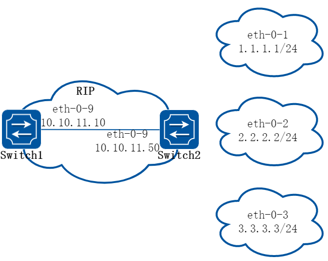
图5-8rip filter list
路由器提供路由信息过滤功能,通过指定访问控制列表和地址前缀列表,可以配置入口或出口过滤策略,对接收或发布的路由进行过滤。一个路由过滤列表通常包括如下参数:
• 一个被用作过滤器的ACL或prefix list。
• 方向。
• In方向:过滤器被应用在学习到的路由上
• Out方向:过滤器被应用在发布的路由上
• 应用过滤器的接口(可选)。
2.配置步骤
步骤 1环境准备, 检查已有配置
Switch1
interface eth-0-9
no switchport
ip address 10.10.11.10/24
!
router rip
network 10.10.11.0/24
Switch2
interface eth-0-1
no switchport
ip address 1.1.1.1/24
!
interface eth-0-2
no switchport
ip address 2.2.2.2/24
!
interface eth-0-3
no switchport
ip address 3.3.3.3/24
!
interface eth-0-9
no switchport
ip address 10.10.11.50/24
!
router rip
network 1.1.1.0/24
network 2.2.2.0/24
network 3.3.3.0/24
network 10.10.11.0/24
Switch1上已学到的路由,显示如下:
Switch1# show ip route
Codes: K - kernel, C - connected, S - static, R - RIP, B - BGP
O - OSPF, IA - OSPF inter area
N1 - OSPF NSSA external type 1, N2 - OSPF NSSA external type 2
E1 - OSPF external type 1, E2 - OSPF external type 2
i - IS-IS, L1 - IS-IS level-1, L2 - IS-IS level-2, ia - IS-IS inter area
[*] - [AD/Metric]
* - candidate default
R 1.1.1.0/24 [120/2] via 10.10.11.50, eth-0-9, 00:01:50
R 2.2.2.0/24 [120/2] via 10.10.11.50, eth-0-9, 00:01:50
R 3.3.3.0/24 [120/2] via 10.10.11.50, eth-0-9, 00:01:50
C 10.10.11.0/24 is directly connected, eth-0-9
C 10.10.11.10/32 is in local loopback, eth-0-9
步骤 2进入配置模式
以下配置在Switch2进行:
Switch2# configure terminal
步骤 3配置过滤列表
Switch2(config)# ip prefix-list 1 deny 1.1.1.0/24
Switch2(config)# ip prefix-list 1 permit any
步骤 4应用过滤列表
Switch2(config)# router rip
Switch2(config-router)# distribute-list prefix 1 out
步骤 5退出配置模式
Switch2(config-router)# end
步骤 6检查配置
Switch1上学到的路由,显示如下:
Switch1# show ip route
Codes: K - kernel, C - connected, S - static, R - RIP, B - BGP
O - OSPF, IA - OSPF inter area
N1 - OSPF NSSA external type 1, N2 - OSPF NSSA external type 2
E1 - OSPF external type 1, E2 - OSPF external type 2
i - IS-IS, L1 - IS-IS level-1, L2 - IS-IS level-2, ia - IS-IS inter area
[*] - [AD/Metric]
* - candidate default
R 2.2.2.0/24 [120/2] via 10.10.11.50, eth-0-9, 00:00:08
R 3.3.3.0/24 [120/2] via 10.10.11.50, eth-0-9, 00:00:08
C 10.10.11.0/24 is directly connected, eth-0-9
C 10.10.11.10/32 is in local loopback, eth-0-9
配置RIPv2验证(single key)
1.组网拓扑
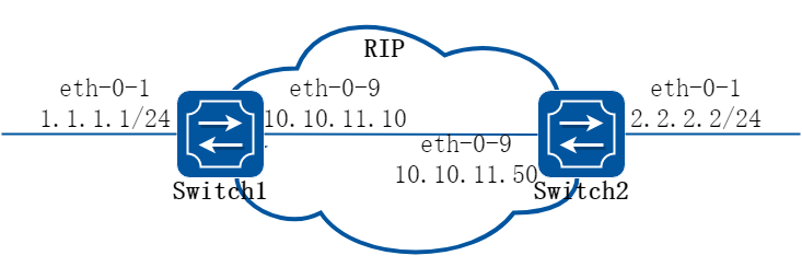
图5-9rip authentication
RIP-2 支持两种认证方式:明文认证和MD5密文认证。这个例子说明如何使用明文进行认证。Switch1和2是在运行RIP路由协议,如果要在交换机上配置明文认证,需要执行如下步骤:
• 指定一个接口,然后定义该接口的密码。
• 指定认证模式为明文。
任何从这个指定接口接收的RIP数据包应该有相同的字符串作为密码。同样的,Switch B上也要定义相同的密码和身份验证模式。
2.配置步骤
步骤 1进入配置模式
Switch# configure terminal
步骤 2进入接口配置模式,配置接口属性和ip地址
Switch1配置:
Switch1(config)# interface eth-0-1
Switch1(config-if)# no switchport
Switch1(config-if)# no shutdown
Switch1(config-if)# ip address 1.1.1.1/24
Switch1(config-if)# exit
Switch1(config-if)# interface eth-0-9
Switch1(config-if)# no switchport
Switch1(config-if)# no shutdown
Switch1(config-if)# ip address 10.10.11.10/24
Switch1(config-if)# exit
Switch2配置:
Switch2(config)# interface eth-0-1
Switch2(config-if)# no switchport
Switch2(config-if)# no shutdown
Switch2(config-if)# ip address 2.2.2.2/24
Switch2(config-if)# exit
Switch2(config-if)# interface eth-0-9
Switch2(config-if)# no switchport
Switch2(config-if)# no shutdown
Switch2(config-if)# ip address 10.10.11.50/24
Switch2(config-if)# exit
步骤 3启用rip路由并配置相关参数
Switch(config)# router rip
Switch(config-router)# network 10.10.11.0/24
Switch(config-router)# redistribute connected
Switch(config-router)# exit
步骤 4指定验证的字符串和模式
Switch(config)# interface eth-0-9
Switch(config-if)# ip rip authentication string Auth1
Switch(config-if)# ip rip authentication mode text
Switch(config-if)# exit
步骤 5退出配置模式
Switch(config)# end
步骤 6检查配置
使用如下命令查看rip数据库:
Switch# show ip rip database
Codes: R - RIP, Rc - RIP connected, Rs - RIP static, K - Kernel,
C - Connected, S - Static, O - OSPF, I - IS-IS, B - BGP
Network Next Hop Metric From If Time
R 2.2.2.0/24 10.10.11.50 2 10.10.11.50 eth-0-9 00:02:52
Rc 10.10.11.0/24
使用如下命令查看rip协议运行状态:
Switch# show ip protocols rip
Routing protocol is "rip"
Sending updates every 30 seconds with +/-5 seconds, next due in 23 seconds
Timeout after 180 seconds, Garbage collect after 120 seconds
Outgoing update filter list for all interface is not set
Incoming update filter list for all interface is not set
Default redistribution metric is 1
Redistributing:
connected metric default
Default version control: send version 2, receive version 2
Interface Send Recv Key-chain
eth-0-9 2 2
Routing for Networks:
10.10.11.0/24
Routing Information Sources:
Gateway Distance Last Update Bad Packets Bad Routes
10.10.11.50 120 00:00:45 1 0
Number of routes (including connected): 2
Distance: (default is 120)
使用如下命令查看rip端口信息:
Switch# show ip rip interface
eth-0-9 is up, line protocol is up
Routing Protocol: RIP
Receive RIP packets
Send RIP packets
Passive interface: Disabled
Split horizon: Enabled with Poisoned Reversed
IP interface address:
10.10.11.10/24
使用如下命令查看设备路由信息:
Switch# show ip route
Codes: K - kernel, C - connected, S - static, R - RIP, B - BGP
O - OSPF, IA - OSPF inter area
N1 - OSPF NSSA external type 1, N2 - OSPF NSSA external type 2
E1 - OSPF external type 1, E2 - OSPF external type 2
i - IS-IS, L1 - IS-IS level-1, L2 - IS-IS level-2, ia - IS-IS inter area
Dc - DHCP Client
[*] - [AD/Metric]
* - candidate default
R 2.2.2.0/24 [120/2] via 10.10.11.50, eth-0-9, 00:02:28
C 10.10.11.0/24 is directly connected, eth-0-9
C 10.10.11.10/32 is in local loopback, eth-0-9
配置RIPv2 MD5 验证 (multiple keys)
1.组网拓扑

图5-10rip authentication
这个例子说明了如何使用MD5进行RIP路由信息交换过程中的验证。对于需要使用MD5认证的Switch A和B来说,首先定义一个钥匙链,然后指定key并且配置认证的字符串或密码,然后通过指定接收或者发送的时间来定义key生效的时间。最后将该钥匙链应用到接口上并且指定接口的认证模式为MD5。Switch A和B的密钥配置必须是一样的才能保证RIP路由更新信息交换成功。在MD5认证中,key ID和key字符串需要同时匹配。在下面的例子中,我们还配置了key生效的时间,这样,每隔5天,key就会更新一次。
2.配置步骤
步骤 1进入配置模式
Switch# configure terminal
步骤 2进入接口配置模式,配置接口属性和ip地址
Switch1配置:
Switch1(config)# interface eth-0-1
Switch1(config-if)# no switchport
Switch1(config-if)# no shutdown
Switch1(config-if)# ip address 1.1.1.1/24
Switch1(config-if)# exit
Switch1(config-if)# interface eth-0-9
Switch1(config-if)# no switchport
Switch1(config-if)# no shutdown
Switch1(config-if)# ip address 10.10.11.10/24
Switch1(config-if)# exit
Switch2配置:
Switch2(config)# interface eth-0-1
Switch2(config-if)# no switchport
Switch2(config-if)# no shutdown
Switch2(config-if)# ip address 2.2.2.2/24
Switch2(config-if)# exit
Switch2(config-if)# interface eth-0-9
Switch2(config-if)# no switchport
Switch2(config-if)# no shutdown
Switch2(config-if)# ip address 10.10.11.50/24
Switch2(config-if)# exit
步骤 3启用rip路由并配置相关参数
Switch(config)# router rip
Switch(config-router)# network 10.10.11.0/24
Switch(config-router)# redistribute connected
Switch(config-router)# exit
步骤 4定义key chain,设置密码和应用的时间范围
Switch(config)# key chain SUN
Switch(config-keychain)# key 1
Switch(config-keychain-key)# key-string key1
Switch(config-keychain-key)# accept-lifetime 12:00:00 Mar 2 2012 14:00:00 Mar 7 2012
Switch(config-keychain-key)# send-lifetime 12:00:00 Mar 2 2012 12:00:00 Mar 7 2012
Switch(config-keychain-key)# exit
第二个key(可选)
Switch(config-keychain)# key 2
Switch(config-keychain-key)# key-string Earth
Switch(config-keychain-key)# accept-lifetime 12:00:00 Mar 7 2012 14:00:00 Mar 12 2012
Switch(config-keychain-key)# send-lifetime 12:00:00 Mar 7 2012 12:00:00 Mar 12 2012
Switch(config-keychain-key)# exit
退出:
Switch(config-keychain)# exit
步骤 5指定验证的字符串和模式
Switch(config)# interface eth-0-9
Switch(config-if)# ip rip authentication key-chain SUN
Switch(config-if)# ip rip authentication mode md5
Switch(config-if)# exit
步骤 6退出配置模式
Switch(config)# end
步骤 7检查配置
使用如下命令查看rip数据库:
Switch# show ip rip database
Codes: R - RIP, Rc - RIP connected, Rs - RIP static, K - Kernel,
C - Connected, S - Static, O - OSPF, I - IS-IS, B - BGP
Network Next Hop Metric From If Time
R 2.2.2.0/24 10.10.11.50 2 10.10.11.50 eth-0-9 00:01:10
Rc 10.10.11.0/24 1 eth-0-9
使用如下命令查看rip协议运行状态:
Switch# show ip protocols rip
Routing protocol is "rip"
Sending updates every 30 seconds with +/-5 seconds, next due in 17 seconds
Timeout after 180 seconds, Garbage collect after 120 seconds
Outgoing update filter list for all interface is not set
Incoming update filter list for all interface is not set
Default redistribution metric is 1
Redistributing:
connected metric default
Default version control: send version 2, receive version 2
Interface Send Recv Key-chain
eth-0-9 2 2 SUN
Routing for Networks:
10.10.11.0/24
Routing Information Sources:
Gateway Distance Last Update Bad Packets Bad Routes
Number of routes (including connected): 2
Distance: (default is 120)
使用如下命令查看rip端口信息:
Switch# show ip rip interface
eth-0-9 is up, line protocol is up
Routing Protocol: RIP
Receive RIP packets
Send RIP packets
Passive interface: Disabled
Split horizon: Enabled with Poisoned Reversed
IP interface address:
10.10.11.10/24
使用下列命令查看设备路由信息:
Switch# show ip route
Codes: K - kernel, C - connected, S - static, R - RIP, B - BGP
O - OSPF, IA - OSPF inter area
N1 - OSPF NSSA external type 1, N2 - OSPF NSSA external type 2
E1 - OSPF external type 1, E2 - OSPF external type 2
i - IS-IS, L1 - IS-IS level-1, L2 - IS-IS level-2, ia - IS-IS inter area
Dc - DHCP Client
[*] - [AD/Metric]
* - candidate default
C 1.1.1.0/24 is directly connected, eth-0-1
C 1.1.1.1/32 is in local loopback, eth-0-1
R 2.2.2.0/24 [120/2] via 10.10.11.50, eth-0-9, 00:02:27
C 10.10.11.0/24 is directly connected, eth-0-9
C 10.10.11.10/32 is in local loopback, eth-0-9
使用如下命令查看key chain 信息:
Switch# show key chain
key chain SUN:
key 1 -- text "key1"
accept-lifetime <12:00:00 Mar 02 2012> - <14:00:00 Mar 07 2012>
send-lifetime <12:00:00 Mar 02 2012> - < 12:00:00 Mar 07 2012>
key 2 -- text "Earth"
accept-lifetime <12:00:00 Mar 07 2012> - <14:00:00 Mar 12 2012>
send-lifetime <12:00:00 Mar 07 2012> - < 12:00:00 Mar 12 2012>
Switch#
5.3.1概述
简介
开放最短路径优先协议OSPF(Open Shortest Path First)是IETF组织开发的一个基于链路状态的内部网关协议,它支持IP子网化以及对外部路由做标记。目前使用的是版本2(RFC2328),其特性如下:
• 适应范围:支持各种规模的网络,最多可支持几百台路由器。
• 快速收敛:在网络的拓扑结构发生变化后立即发送更新报文,使这一变化在自治系统中同步。
• 无自环:由于OSPF 根据收集到的链路状态用最短路径树算法计算路由,从算法本身保证了不会生成自环路由。
• 区域划分:允许自治系统的网络被划分成区域来管理,区域间传送的路由信息被进一步抽象,从而减少了占用的网络带宽。
• 等价路由:支持到同一目的地址的多条等价路由。
• 路由分级:使用4 类不同的路由,按优先顺序来说分别是:区域内路由、区域间路由、第一类外部路由、第二类外部路由。
• 支持验证:支持基于接口的报文验证以保证路由计算的安全性。
• 组播发送:协议报文支持以组播形式发送。
当前的系统支持如下OSPF特性:
• 支持末梢区域:支持路由重分布,这包括将其他路由协议学到的路由导入OSPF或者将OSPF学到的路由导出到其他路由协议中。
• 支持明文和MD5两种认证模式:支持OSPF interface上的参数配置,包括输出度量值,重传时间,发送延时时间,路由器优先级,路由器hello报文时间间隔,认证密码等等。
OSPF需要多个路由器协同工作,包括区域边界路由器(ABR),自治系统边界路由器(ASBR),内部路由器等。最简单的OSPF配置只需要使用默认的参数,并且将所有的OSPF interface加入同一个区域就可以了。
原理描述
参考 RFC 2328。
5.3.2配置举例
配置基本OSPF
步骤 1进入配置模式
Switch# configure terminal
步骤 2创建ospf实例,发布需要的网段到指定域
Switch(config)# router ospf 100
Switch(config-router)# network 10.10.10.0/24 area 0
Switch(config-router)# quit
说明:删除该ospf实例的方法为
Switch(config)# no router ospf 100
步骤 3退出配置模式
Switch(config)# end
步骤 4检查配置
Switch# show ip protocols
Routing Protocol is "ospf 100"
Redistributing:
Routing for Networks:
10.10.10.0/24
Distance: (default is 110)
启用OSPF
1.组网拓扑
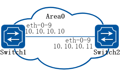
图5-11ospf
这个例子显示了一个接口上启用OSPF所需的最低配置。
![]() 一个接口只能属于一个区域,不同的接口可以属于不同的区域
一个接口只能属于一个区域,不同的接口可以属于不同的区域
2.配置步骤
步骤 1进入配置模式
Switch# configure terminal
步骤 2进入接口配置模式,配置接口属性和ip地址
在Switch1配置:
Switch1(config)# interface eth-0-9
Switch1(config-if)# no switchport
Switch1(config-if)# no shutdown
Switch1(config-if)# ip address 10.10.10.10/24
Switch1(config-if)# exit
在Switch2配置:
Switch2(config)# interface eth-0-9
Switch2(config-if)# no switchport
Switch2(config-if)# no shutdown
Switch2(config-if)# ip address 10.10.10.11/24
Switch2(config-if)# exit
步骤 3创建ospf实例,发布需要的网段到指定域
在Switch1配置:
Switch1(config)# router ospf 100
Switch1(config-router)# network 10.10.10.0/24 area 0
在Switch2配置:
Switch2(config)# router ospf 200
Switch2(config-router)# network 10.10.10.0/24 area 0
说明:直连的两个设备配置ospf,area必须相同。ospf的实例号可以相同也可以不同。
步骤 4退出配置模式
Switch(config-router)# end
步骤 5检查配置
使用下列命令查看ospf数据库:
Switch# show ip ospf database
OSPF Router with ID (10.10.10.10) (Process ID 100)
Router Link States (Area 0)
Link ID ADV Router Age Seq# CkSum Link count
10.10.10.10 10.10.10.10 26 0x80000006 0x1499 1
10.10.10.11 10.10.10.11 27 0x80000003 0x1895 1
Net Link States (Area 0)
Link ID ADV Router Age Seq# CkSum
10.10.10.10 10.10.10.10 26 0x80000001 0xdfd8
使用下列命令查看ospf端口状态:
Switch# show ip ospf interface
eth-0-9 is up, line protocol is up
Internet Address 10.10.10.10/24, Area 0, MTU 1500
Process ID 100, Router ID 10.10.10.10, Network Type BROADCAST, Cost: 1
Transmit Delay is 1 sec, State DR, Priority 1, TE Metric 1
Designated Router (ID) 10.10.10.10, Interface Address 10.10.10.10
Backup Designated Router (ID) 10.10.10.11, Interface Address 10.10.10.11
Timer intervals configured, Hello 10, Dead 40, Wait 40, Retransmit 5
Hello due in 00:00:06
Neighbor Count is 1, Adjacent neighbor count is 1
Crypt Sequence Number is 1527047183
Hello received 25 sent 576, DD received 4 sent 4
LS-Req received 1 sent 1, LS-Upd received 3 sent 3
LS-Ack received 2 sent 2, Discarded 0
使用下列命令查看ospf邻居:
Switch1:
Switch1# show ip ospf neighbor
OSPF process 100:
Neighbor ID Pri State Dead Time Address Interface
10.10.10.11 1 Full/Backup 00:00:33 10.10.10.11 eth-0-9
Switch2:
Switch2# show ip ospf neighbor
OSPF process 200:
Neighbor ID Pri State Dead Time Address Interface
10.10.10.10 1 Full/DR 00:00:33 10.10.10.10 eth-0-9
使用下列命令查看ospf路由:
Switch# show ip ospf route
OSPF process 100:
Codes: C - connected, D - Discard, O - OSPF, IA - OSPF inter area
N1 - OSPF NSSA external type 1, N2 - OSPF NSSA external type 2
E1 - OSPF external type 1, E2 - OSPF external type 2
C 10.10.10.0/24 [1] is directly connected, eth-0-9, Area 0
配置优先级
1.组网拓扑
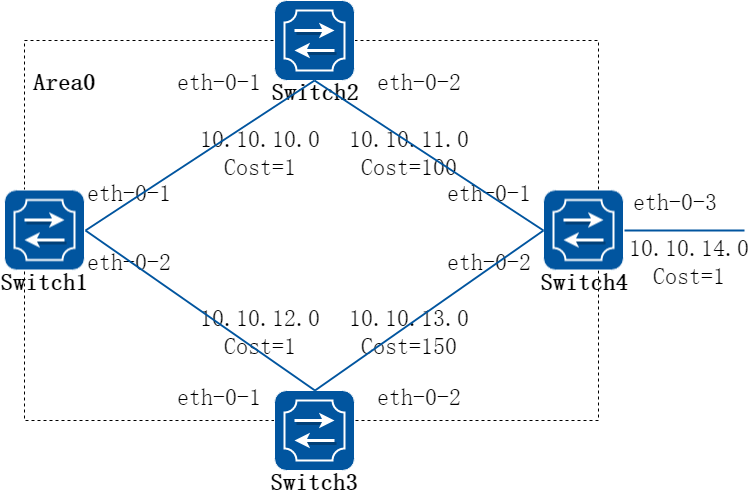
图5-12ospf priority
这个例子主要讲述了如何配置接口优先级,优先级高的成为DR。优先级为0的不参与DR选举。Switch3的优先级是10,这比Switch1和Switch2的默认优先级1要高,因此Switch3将成为这个网络内的DR。
2.配置步骤
步骤 1进入配置模式
Switch# configure terminal
步骤 2进入接口配置模式,配置接口属性和ip地址
在Switch1配置:
Switch1(config)# interface eth-0-17
Switch1(config-if)# no switchport
Switch1(config-if)# no shutdown
Switch1(config-if)# ip address 10.10.10.10/24
Switch1(config-if)# quit
在Switch2配置:
Switch2(config)# interface eth-0-13
Switch2(config-if)# no switchport
Switch2(config-if)# no shutdown
Switch2(config-if)# ip address 10.10.10.11/24
Switch2(config-if)# quit
在Switch3配置:
Switch3(config)# interface eth-0-9
Switch3(config-if)# no switchport
Switch3(config-if)# no shutdown
Switch3(config-if)# ip address 10.10.10.13/24
Switch3(config-if)# quit
在L2 switch 配置:
Switch4(config)# interface eth-0-9
Switch4(config-if)# no shutdown
Switch4(config-if)# quit
Switch4(config)# interface eth-0-13
Switch4(config-if)# no shutdown
Switch4(config-if)# quit
Switch4(config)# interface eth-0-17
Switch4(config-if)# no shutdown
Switch4(config-if)# quit
步骤 3配置ospf接口优先级
在Switch3配置:
Switch3(config)# interface eth-0-9
Switch3(config-if)# ip ospf priority 10
Switch3(config-if)# quit
步骤 4创建ospf实例,发布需要的网段到指定域
Switch(config)# router ospf 100
Switch(config-router)# network 10.10.10.0/24 area 0
Switch(config-if)# quit
步骤 5退出配置模式
Switch(config)# end
步骤 6检查配置
使用下列命令查看ospf邻居:
Switch1:
Switch1# show ip ospf neighbor
OSPF process 100:
Neighbor ID Pri State Dead Time Address Interface
10.10.10.11 1 Full/Backup 00:00:31 10.10.10.11 eth-0-17
10.10.10.13 10 Full/DR 00:00:38 10.10.10.13 eth-0-17
Switch2:
Switch2# show ip ospf neighbor
OSPF process 100:
Neighbor ID Pri State Dead Time Address Interface
10.10.10.10 1 Full/DROther 00:00:39 10.10.10.10 eth-0-13
10.10.10.13 10 Full/DR 00:00:32 10.10.10.13 eth-0-13
Switch3:
Switch3# show ip ospf neighbor
OSPF process 100:
Neighbor ID Pri State Dead Time Address Interface
10.10.10.10 1 Full/DROther 00:00:37 10.10.10.10 eth-0-9
10.10.10.11 1 Full/Backup 00:00:32 10.10.10.11 eth-0-9
使用下列命令查看ospf端口状态:
Switch1:
Switch1# show ip ospf interface
eth-0-17 is up, line protocol is up
Internet Address 10.10.10.10/24, Area 0, MTU 1500
Process ID 100, Router ID 10.10.10.10, Network Type BROADCAST, Cost: 1
Transmit Delay is 1 sec, State DROther, Priority 1, TE Metric 1
Designated Router (ID) 10.10.10.13, Interface Address 10.10.10.13
Backup Designated Router (ID) 10.10.10.11, Interface Address 10.10.10.11
Timer intervals configured, Hello 10, Dead 40, Wait 40, Retransmit 5
Hello due in 00:00:10
Neighbor Count is 2, Adjacent neighbor count is 2
Crypt Sequence Number is 1527056133
Hello received 106 sent 54, DD received 8 sent 9
LS-Req received 2 sent 3, LS-Upd received 8 sent 5
LS-Ack received 9 sent 5, Discarded 3
Switch2:
Switch2# show ip ospf interface
eth-0-13 is up, line protocol is up
Internet Address 10.10.10.11/24, Area 0, MTU 1500
Process ID 100, Router ID 10.10.10.11, Network Type BROADCAST, Cost: 1
Transmit Delay is 1 sec, State Backup, Priority 1, TE Metric 1
Designated Router (ID) 10.10.10.13, Interface Address 10.10.10.13
Backup Designated Router (ID) 10.10.10.11, Interface Address 10.10.10.11
Timer intervals configured, Hello 10, Dead 40, Wait 40, Retransmit 5
Hello due in 00:00:10
Neighbor Count is 2, Adjacent neighbor count is 2
Crypt Sequence Number is 1527056130
Hello received 110 sent 56, DD received 8 sent 7
LS-Req received 3 sent 2, LS-Upd received 12 sent 6
LS-Ack received 11 sent 8, Discarded 0
Switch3:
Switch3# show ip ospf interface
eth-0-9 is up, line protocol is up
Internet Address 10.10.10.13/24, Area 0, MTU 1500
Process ID 100, Router ID 10.10.10.13, Network Type BROADCAST, Cost: 1
Transmit Delay is 1 sec, State DR, Priority 10, TE Metric 1
Designated Router (ID) 10.10.10.13, Interface Address 10.10.10.13
Backup Designated Router (ID) 10.10.10.11, Interface Address 10.10.10.11
Timer intervals configured, Hello 10, Dead 40, Wait 40, Retransmit 5
Hello due in 00:00:01
Neighbor Count is 2, Adjacent neighbor count is 2
Crypt Sequence Number is 1527056127
Hello received 32 sent 16, DD received 9 sent 9
LS-Req received 2 sent 2, LS-Upd received 11 sent 8
LS-Ack received 10 sent 8, Discarded 0
配置OSPF区域参数
1.组网拓扑
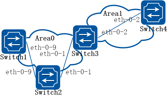
图5-13ospf area
您可以选择性地配置多个OSPF区域参数。这些参数包括用于防止访问未经授权的区域的认证密码,以及将区域配置为末梢区域(Stub)。Stub区域是一些特定的区域,Stub区域的ABR不传播它们接收到的自治系统外部路由,在这些区域中路由器的路由表规模以及路由信息传递的数量都会大大减少。为保证到自治系统外的路由依旧可达,该区域的ABR将生成一条缺省路由,并发布给Stub 区域中的其他非ABR路由器。
路由聚合是指ABR或ASBR将具有相同前缀的路由信息聚合,只发布一条路由到其它区域。AS被划分成不同的区域后,区域间可以通过路由聚合来减少路由信息,减小路由表的规模,提高路由器的运算速度。如果网络号是连续的,你可以使用area range命令将这些连续的网段聚合成一个网段。这样ABR 只发送一条聚合后的LSA,所有属于本命令指定的聚合网段范围的LSA 将不再会被单独发送出去,这样可减少其它区域中LSDB的规模。
2.配置步骤
步骤 1进入配置模式
Switch# configure terminal
步骤 2进入接口配置模式,配置接口属性和ip地址
在Switch1配置:
Switch1(config)# interface eth-0-17
Switch1(config-if)# no switchport
Switch1(config-if)# no shutdown
Switch1(config-if)# ip address 10.10.10.10/24
Switch1(config-if)# quit
在Switch2配置:
Switch2(config)# interface eth-0-13
Switch2(config-if)# no switchport
Switch2(config-if)# no shutdown
Switch2(config-if)# ip address 10.10.10.11/24
Switch2(config-if)# quit
Switch2(config)# interface eth-0-21
Switch2(config-if)# no switchport
Switch2(config-if)# no shutdown
Switch2(config-if)# ip address 10.10.11.11/24
Switch2(config-if)# quit
在Switch3配置:
Switch3(config)# interface eth-0-9
Switch3(config-if)# no switchport
Switch3(config-if)# no shutdown
Switch3(config-if)# ip address 10.10.10.13/24
Switch3(config-if)# quit
在Switch4配置:
Switch4(config)# interface eth-0-21
Switch4(config-if)# no switchport
Switch4(config-if)# no shutdown
Switch4(config-if)# ip address 10.10.11.12/24
Switch4(config-if)# quit
在L2 switch 配置:
Switch5(config)# interface eth-0-9
Switch5(config-if)# no shutdown
Switch5(config-if)# quit
Switch5(config)# interface eth-0-13
Switch5(config-if)# no shutdown
Switch5(config-if)# quit
Switch5(config)# interface eth-0-17
Switch5(config-if)# no shutdown
Switch5(config-if)# quit
步骤 3配置ospf接口优先级
在Switch3配置:
Switch3(config)# interface eth-0-9
Switch3(config-if)# ip ospf priority 10
Switch3(config-if)# quit
步骤 4创建ospf实例,发布需要的网段到指定域
在Switch1配置:
Switch1(config)# router ospf 100
Switch1(config-router)# network 10.10.10.0/24 area 0
Switch1(config-router)# quit
在Switch2配置:
Switch2(config)# router ospf 100
Switch2(config-router)# network 10.10.10.0/24 area 0
Switch2(config-router)# network 10.10.11.0/24 area 1
Switch2(config-router)# area 0 range 10.10.10.0/24
Switch2(config-router)# area 1 stub no-summary
Switch2(config-router)# quit
在Switch3配置:
Switch3(config)# router ospf 100
Switch3(config-router)# network 10.10.10.0/24 area 0
Switch3(config-router)# quit
在Switch4配置:
Switch4(config)# router ospf 200
Switch4(config-router)# network 10.10.11.0/24 area 1
Switch4(config-router)# area 1 stub no-summary
Switch4(config-router)# quit
步骤 5退出配置模式
Switch(config)# end
步骤 6检查配置
使用下列命令查看ospf路由:
Switch1:
Switch1# show ip route
Codes: K - kernel, C - connected, S - static, R - RIP, B - BGP
O - OSPF, IA - OSPF inter area
N1 - OSPF NSSA external type 1, N2 - OSPF NSSA external type 2
E1 - OSPF external type 1, E2 - OSPF external type 2
i - IS-IS, L1 - IS-IS level-1, L2 - IS-IS level-2, ia - IS-IS inter area
Dc - DHCP Client
[*] - [AD/Metric]
* - candidate default
C 10.10.10.0/24 is directly connected, eth-0-17
C 10.10.10.10/32 is in local loopback, eth-0-17
O IA 10.10.11.0/24 [110/2] via 10.10.10.11, eth-0-17, 00:00:04
Switch2:
Switch2# show ip route
Codes: K - kernel, C - connected, S - static, R - RIP, B - BGP
O - OSPF, IA - OSPF inter area
N1 - OSPF NSSA external type 1, N2 - OSPF NSSA external type 2
E1 - OSPF external type 1, E2 - OSPF external type 2
i - IS-IS, L1 - IS-IS level-1, L2 - IS-IS level-2, ia - IS-IS inter area
Dc - DHCP Client
[*] - [AD/Metric]
* - candidate default
C 10.10.10.0/24 is directly connected, eth-0-13
C 10.10.10.11/32 is in local loopback, eth-0-13
C 10.10.11.0/24 is directly connected, eth-0-21
C 10.10.11.11/32 is in local loopback, eth-0-21
Switch3:
Switch3# show ip route
Codes: K - kernel, C - connected, S - static, R - RIP, B - BGP
O - OSPF, IA - OSPF inter area
N1 - OSPF NSSA external type 1, N2 - OSPF NSSA external type 2
E1 - OSPF external type 1, E2 - OSPF external type 2
i - IS-IS, L1 - IS-IS level-1, L2 - IS-IS level-2, ia - IS-IS inter area
Dc - DHCP Client
[*] - [AD/Metric]
* - candidate default
C 10.10.10.0/24 is directly connected, eth-0-9
C 10.10.10.13/32 is in local loopback, eth-0-9
O IA 10.10.11.0/24 [110/2] via 10.10.10.11, eth-0-9, 00:06:29
Switch4:
Switch4# show ip route
Codes: K - kernel, C - connected, S - static, R - RIP, B - BGP
O - OSPF, IA - OSPF inter area
N1 - OSPF NSSA external type 1, N2 - OSPF NSSA external type 2
E1 - OSPF external type 1, E2 - OSPF external type 2
i - IS-IS, L1 - IS-IS level-1, L2 - IS-IS level-2, ia - IS-IS inter area
Dc - DHCP Client
[*] - [AD/Metric]
* - candidate default
Gateway of last resort is 10.10.11.11 to network 0.0.0.0
O*IA 0.0.0.0/0 [110/2] via 10.10.11.11, eth-0-21, 00:12:46
C 10.10.10.0/24 is directly connected, eth-0-21
C 10.10.10.12/32 is in local loopback, eth-0-21
配置OSPF重分布路由
1.组网拓扑
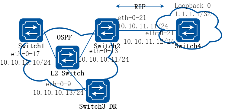
图5-14ospf redistribute
区域内和区域间路由描述的是AS 内部的网络结构,外部路由则描述了应该如何选择到AS 以外目的地址的路由。OSPF 将引入的AS 外部路由分为两类:Type1 和Type2。
第一类外部路由是指接收的是IGP(Interior Gateway Protocol,内部网关协议)路由(例如静态路由和RIP 路由)。由于这类路由的可信程度较高,并且和OSPF 自身路由的开销具有可比性,所以到第一类外部路由的开销等于本路由器到相应的ASBR 的开销与ASBR 到该路由目的地址的开销之和。
第二类外部路由是指接收的是EGP(Exterior Gateway Protocol,外部网关协议)路由。由于这类路由的可信度比较低,所以OSPF 协议认为从ASBR 到自治系统之外的开销远远大于在自治系统之内到达ASBR 的开销。所以计算路由开销时将主要考虑前者,即到第二类外部路由的开销等于ASBR 到该路由目的地址的开销。如果计算出开销值相等的两条路由,再考虑本路由器到相应的ASBR 的开销。下面例子RIP路由将作为外部路由被重分布到OSPF网络中。
2.配置步骤
步骤 1进入配置模式
Switch# configure terminal
步骤 2进入接口配置模式,配置接口属性和ip地址
在Switch1配置:
Switch1(config)# interface eth-0-17
Switch1(config-if)# no switchport
Switch1(config-if)# no shutdown
Switch1(config-if)# ip address 10.10.10.10/24
Switch1(config-if)# quit
在Switch2配置:
Switch2(config)# interface eth-0-13
Switch2(config-if)# no switchport
Switch2(config-if)# no shutdown
Switch2(config-if)# ip address 10.10.10.11/24
Switch2(config-if)# quit
Switch2(config)# interface eth-0-21
Switch2(config-if)# no switchport
Switch2(config-if)# no shutdown
Switch2(config-if)# ip address 10.10.11.11/24
Switch2(config-if)# quit
在Switch3配置:
Switch3(config)# interface eth-0-9
Switch3(config-if)# no switchport
Switch3(config-if)# no shutdown
Switch3(config-if)# ip address 10.10.10.13/24
Switch3(config-if)# quit
在Switch4配置:
Switch4(config)# interface eth-0-21
Switch4(config-if)# no switchport
Switch4(config-if)# no shutdown
Switch4(config-if)# ip address 10.10.11.12/24
Switch4(config-if)# quit
Switch4(config)# interface loopback 0
Switch4(config-if)# ip address 1.1.1.1/32
Switch4(config-if)# quit
在L2 switch 配置:
Switch5(config)# interface eth-0-9
Switch5(config-if)# no shutdown
Switch5(config-if)# quit
Switch5(config)# interface eth-0-13
Switch5(config-if)# no shutdown
Switch5(config-if)# quit
Switch5(config)# interface eth-0-17
Switch5(config-if)# no shutdown
Switch5(config-if)# quit
步骤 3配置ospf接口优先级
在Switch3配置:
Switch3(config)# interface eth-0-9
Switch3(config-if)# ip ospf priority 10
Switch3(config-if)# quit
步骤 4创建ospf实例,发布需要的网段到指定域
在Switch1配置:
Switch1(config)# router ospf 100
Switch1(config-router)# network 10.10.10.0/24 area 0
Switch1(config-router)# quit
在Switch2配置:
Switch2(config)# router ospf 100
Switch2(config-router)# network 10.10.10.0/24 area 0
Switch2(config-router)# redistribute connected
Switch2(config-router)# redistribute rip
Switch2(config-router)# quit
在Switch3配置:
Switch3(config)# router ospf 100
Switch3(config-router)# network 10.10.10.0/24 area 0
Switch3(config-router)# quit
步骤 5创建rip实例,发布需要的网段
在Switch2配置:
Switch2(config)# router rip
Switch2(config-router)# network 10.10.11.0/24
Switch2(config-router)#redistribute connected
Switch2(config-router)# quit
在Switch4配置:
Switch4(config)# router rip
Switch4(config-router)# network 10.10.11.0/24
Switch4(config-router)# network 1.1.1.1/32
Switch4(config-router)# redistribute connected
Switch4(config-router)# quit
步骤 6退出配置模式
Switch(config)# end
步骤 7检查配置
使用下列命令查看ospf路由:
Switch1:
Switch1# show ip route
Codes: K - kernel, C - connected, S - static, R - RIP, B - BGP
O - OSPF, IA - OSPF inter area
N1 - OSPF NSSA external type 1, N2 - OSPF NSSA external type 2
E1 - OSPF external type 1, E2 - OSPF external type 2
i - IS-IS, L1 - IS-IS level-1, L2 - IS-IS level-2, ia - IS-IS inter area
Dc - DHCP Client
[*] - [AD/Metric]
* - candidate default
O E2 1.1.1.1/32 [110/20] via 10.10.10.11, eth-0-17, 00:01:54
C 10.10.10.0/24 is directly connected, eth-0-17
C 10.10.10.10/32 is in local loopback, eth-0-17
O E2 10.10.11.0/24 [110/20] via 10.10.10.11, eth-0-17, 00:03:49
Switch2:
Switch2# show ip route
Codes: K - kernel, C - connected, S - static, R - RIP, B - BGP
O - OSPF, IA - OSPF inter area
N1 - OSPF NSSA external type 1, N2 - OSPF NSSA external type 2
E1 - OSPF external type 1, E2 - OSPF external type 2
i - IS-IS, L1 - IS-IS level-1, L2 - IS-IS level-2, ia - IS-IS inter area
Dc - DHCP Client
[*] - [AD/Metric]
* - candidate default
R 1.1.1.1/32 [120/2] via 10.10.11.12, eth-0-21, 00:02:27
C 10.10.10.0/24 is directly connected, eth-0-13
C 10.10.10.11/32 is in local loopback, eth-0-13
C 10.10.11.0/24 is directly connected, eth-0-21
C 10.10.11.11/32 is in local loopback, eth-0-21
Switch3:
Switch3# show ip route
Codes: K - kernel, C - connected, S - static, R - RIP, B - BGP
O - OSPF, IA - OSPF inter area
N1 - OSPF NSSA external type 1, N2 - OSPF NSSA external type 2
E1 - OSPF external type 1, E2 - OSPF external type 2
i - IS-IS, L1 - IS-IS level-1, L2 - IS-IS level-2, ia - IS-IS inter area
Dc - DHCP Client
[*] - [AD/Metric]
* - candidate default
O E2 1.1.1.1/32 [110/20] via 10.10.10.11, eth-0-9, 00:03:01
C 10.10.10.0/24 is directly connected, eth-0-9
C 10.10.10.13/32 is in local loopback, eth-0-9
O E2 10.10.11.0/24 [110/20] via 10.10.10.11, eth-0-9, 00:04:57
Switch4:
Switch4# show ip route
Codes: K - kernel, C - connected, S - static, R - RIP, B - BGP
O - OSPF, IA - OSPF inter area
N1 - OSPF NSSA external type 1, N2 - OSPF NSSA external type 2
E1 - OSPF external type 1, E2 - OSPF external type 2
i - IS-IS, L1 - IS-IS level-1, L2 - IS-IS level-2, ia - IS-IS inter area
Dc - DHCP Client
[*] - [AD/Metric]
* - candidate default
C 1.1.1.1/32 is directly connected, loopback0
R 10.10.10.0/24 [120/2] via 10.10.11.11, eth-0-21, 00:17:36
C 10.10.11.0/24 is directly connected, eth-0-21
C 10.10.11.12/32 is in local loopback, eth-0-21
使用下列命令查看ospf数据库:
Switch1:
Switch1# show ip ospf database external
OSPF Router with ID (10.10.10.10) (Process ID 100)
AS External Link States
LS age: 317
Options: 0x2 (*|-|-|-|-|-|E|-)
LS Type: AS-external-LSA
Link State ID: 1.1.1.1 (External Network Number)
Advertising Router: 10.10.10.11
LS Seq Number: 80000001
Checksum: 0x4a47
Length: 36
Network Mask: /32
Metric Type: 2 (Larger than any link state path)
TOS: 0
Metric: 20
Forward Address: 0.0.0.0
External Route Tag: 0
LS age: 438
Options: 0x2 (*|-|-|-|-|-|E|-)
LS Type: AS-external-LSA
Link State ID: 10.10.11.0 (External Network Number)
Advertising Router: 10.10.10.11
LS Seq Number: 80000001
Checksum: 0x0472
Length: 36
Network Mask: /24
Metric Type: 2 (Larger than any link state path)
TOS: 0
Metric: 20
Forward Address: 0.0.0.0
External Route Tag: 0
Switch2:
Switch2# show ip ospf database external
OSPF Router with ID (10.10.10.11) (Process ID 100)
AS External Link States
LS age: 367
Options: 0x2 (*|-|-|-|-|-|E|-)
LS Type: AS-external-LSA
Link State ID: 1.1.1.1 (External Network Number)
Advertising Router: 10.10.10.11
LS Seq Number: 80000001
Checksum: 0x4a47
Length: 36
Network Mask: /32
Metric Type: 2 (Larger than any link state path)
TOS: 0
Metric: 20
Forward Address: 0.0.0.0
External Route Tag: 0
LS age: 487
Options: 0x2 (*|-|-|-|-|-|E|-)
LS Type: AS-external-LSA
Link State ID: 10.10.11.0 (External Network Number)
Advertising Router: 10.10.10.11
LS Seq Number: 80000001
Checksum: 0x0472
Length: 36
Network Mask: /24
Metric Type: 2 (Larger than any link state path)
TOS: 0
Metric: 20
Forward Address: 0.0.0.0
External Route Tag: 0
Switch3:
Switch3# show ip ospf database external
OSPF Router with ID (10.10.10.13) (Process ID 100)
AS External Link States
LS age: 396
Options: 0x2 (*|-|-|-|-|-|E|-)
LS Type: AS-external-LSA
Link State ID: 1.1.1.1 (External Network Number)
Advertising Router: 10.10.10.11
LS Seq Number: 80000001
Checksum: 0x4a47
Length: 36
Network Mask: /32
Metric Type: 2 (Larger than any link state path)
TOS: 0
Metric: 20
Forward Address: 0.0.0.0
External Route Tag: 0
LS age: 517
Options: 0x2 (*|-|-|-|-|-|E|-)
LS Type: AS-external-LSA
Link State ID: 10.10.11.0 (External Network Number)
Advertising Router: 10.10.10.11
LS Seq Number: 80000001
Checksum: 0x0472
Length: 36
Network Mask: /24
Metric Type: 2 (Larger than any link state path)
TOS: 0
Metric: 20
Forward Address: 0.0.0.0
External Route Tag: 0
配置OSPF Cost
1.组网拓扑

图5-15ospf cost
用户可以通过修改接口的COST值来使路由成为最优路由。在下面的例子中,通过修改COST值可以使Switch2成为Switch1的下一跳。
默认接口的COST值是1(1000M speed)。Switch2的eth-0-2优先级100,Switch3的eth-0-2优先级150. 那么到达Switch4的网络10.10.14.0的Cost值将不一样:
Switch2: 1+1+100 = 102
Switch3: 1+1+150 = 152
2.配置步骤
步骤 1进入配置模式
Switch# configure terminal
步骤 2进入接口配置模式,配置接口属性和ip地址。在接口配置模式下,设置该接口的ospf cost值
在Switch1配置:
Switch1(config)# interface eth-0-1
Switch1(config-if)# no switchport
Switch1(config-if)# ip address 10.10.10.1/24
Switch1(config-if)# exit
Switch1(config)# interface eth-0-2
Switch1(config-if)# no switchport
Switch1(config-if)# ip address 10.10.12.1/24
Switch1(config-if)# exit
在Switch2配置:
Switch2(config)# interface eth-0-1
Switch2(config-if)# no switchport
Switch2(config-if)# ip address 10.10.10.2/24
Switch2(config-if)# exit
Switch2(config)# interface eth-0-2
Switch2(config-if)# no switchport
Switch2(config-if)# ip address 10.10.11.2/24
Switch2(config-if)# ip ospf cost 100
Switch2(config-if)# exit
在Switch3配置:
Switch3(config)# interface eth-0-1
Switch3(config-if)# no switchport
Switch3(config-if)# ip address 10.10.12.2/24
Switch3(config-if)# exit
Switch3(config)# interface eth-0-2
Switch3(config-if)# no switchport
Switch3(config-if)# ip address 10.10.13.2/24
Switch3(config-if)# ip ospf cost 150
Switch3(config-if)# exit
在Switch4配置:
Switch4(config)# interface eth-0-1
Switch4(config-if)# no switchport
Switch4(config-if)# ip address 10.10.11.1/24
Switch4(config-if)# exit
Switch4(config)# interface eth-0-2
Switch4(config-if)# no switchport
Switch4(config-if)# ip address 10.10.13.1/24
Switch4(config-if)# exit
Switch4(config)# interface eth-0-3
Switch4(config-if)# no switchport
Switch4(config-if)# ip address 10.10.14.1/24
Switch4(config-if)# exit
步骤 3创建ospf实例,发布需要的网段到指定域
在Switch1配置:
Switch1(config)# router ospf 100
Switch1(config-router)# network 10.10.10.0/24 area 0
Switch1(config-router)# network 10.10.12.0/24 area 0
Switch1(config-router)# exit
在Switch2配置:
Switch2(config)# router ospf 100
Switch2(config-router)# network 10.10.10.0/24 area 0
Switch2(config-router)# network 10.10.11.0/24 area 0
Switch2(config-router)# exit
在Switch3配置:
Switch3(config)# router ospf 100
Switch3(config-router)# network 10.10.12.0/24 area 0
Switch3(config-router)# network 10.10.13.0/24 area 0
Switch3(config-router)# exit
在Switch4配置:
Switch4(config)# router ospf 100
Switch4(config-router)# network 10.10.11.0/24 area 0
Switch4(config-router)# network 10.10.13.0/24 area 0
Switch4(config-router)# network 10.10.14.0/24 area 0
Switch4(config-router)# exit
步骤 4退出配置模式
Switch(config)# end
步骤 5检查配置
使用下列命令查看ospf路由:
Switch1:
Switch1# show ip ospf route
OSPF process 0:
Codes: C - connected, D - Discard, O - OSPF, IA - OSPF inter area
N1 - OSPF NSSA external type 1, N2 - OSPF NSSA external type 2
E1 - OSPF external type 1, E2 - OSPF external type 2
C 10.10.10.0/24 [1] is directly connected, eth-0-1, Area 0
O 10.10.11.0/24 [101] via 10.10.10.2, eth-0-1, Area 0
C 10.10.12.0/24 [1] is directly connected, eth-0-2, Area 0
O 10.10.13.0/24 [102] via 10.10.10.2, eth-0-1, Area 0
O 10.10.14.0/24 [102] via 10.10.10.2, eth-0-1, Area 0
Switch2:
Switch2# show ip ospf route
OSPF process 100:
Codes: C - connected, D - Discard, O - OSPF, IA - OSPF inter area
N1 - OSPF NSSA external type 1, N2 - OSPF NSSA external type 2
E1 - OSPF external type 1, E2 - OSPF external type 2
C 10.10.10.0/24 [10] is directly connected, eth-0-1, Area 0
C 10.10.11.0/24 [100] is directly connected, eth-0-2, Area 0
O 10.10.12.0/24 [11] via 10.10.10.1, eth-0-1, Area 0
O 10.10.13.0/24 [101] via 10.10.11.1, eth-0-2, Area 0
O 10.10.14.0/24 [101] via 10.10.11.1, eth-0-2, Area 0
Switch3:
Switch3# show ip ospf route
OSPF process 100:
Codes: C - connected, D - Discard, O - OSPF, IA - OSPF inter area
N1 - OSPF NSSA external type 1, N2 - OSPF NSSA external type 2
E1 - OSPF external type 1, E2 - OSPF external type 2
O 10.10.10.0/24 [1] via 10.10.12.1, eth-0-1, Area 0
O 10.10.11.0/24 [101] via 10.10.12.1, eth-0-1, Area 0
C 10.10.12.0/24 [1] is directly connected, eth-0-1, Area 0
O 10.10.13.0/24 [102] via 10.10.12.1, eth-0-1, Area 0
O 10.10.14.0/24 [102] via 10.10.12.1, eth-0-1, Area 0
Switch4:
Switch4# show ip route
Codes: K - kernel, C - connected, S - static, R - RIP, B - BGP
O - OSPF, IA - OSPF inter area
N1 - OSPF NSSA external type 1, N2 - OSPF NSSA external type 2
E1 - OSPF external type 1, E2 - OSPF external type 2
i - IS-IS, L1 - IS-IS level-1, L2 - IS-IS level-2, ia - IS-IS inter area
[*] - [AD/Metric]
* - candidate default
O 10.10.10.0/24 [110/1] via 10.10.11.2, eth-0-1, 00:06:27
C 10.10.11.0/24 is directly connected, eth-0-1
O 10.10.12.0/24 [110/1] via 10.10.13.2, eth-0-2, 00:06:17
C 10.10.13.0/24 is directly connected, eth-0-2
C 10.10.14.0/24 is directly connected, eth-0-3
配置OSPF认证
1.组网拓扑

图5-16ospf authentication
系统目前支持三种类型的OSPF认证: 无认证(类型0),明文认证(类型1)和MD5认证(类型2)。无认证,网络中的路由信息交换不需要经过任何认证。明文认证,所有的路由器上配置的认证模式和密码都必须是一样的。MD5认证,你需要在每台路由器上配置相同的密钥和密钥ID。路由器会根据密钥,密钥ID和OSPF报文内容生成消息摘要加到OSPF报文里面。
认证类型可以基于area配置,也可以基于interface 配置,这两者可以同时使用。如果interface上配置的认证类型和区域内配置的认证类型不一样,则优先使用interface上的认证类型。如果interface上没有配置认证类型,那么就使用区域内配置的认证类型。.
下面例子简单介绍了下OSPF的三种类型的验证。Switch1和Switch2之间不使用认证;Switch2和Switch3之间使用明文认证;Switch3和Switch4之间使用MD5认证。
2.配置步骤
步骤 1进入配置模式
Switch# configure terminal
步骤 2进入接口配置模式,配置接口属性和ip地址。在接口配置模式下,设置该接口的认证类型
在Switch1配置:
Switch1(config)#interface eth-0-9
Switch1(config-if)#no switchport
Switch1(config-if)#ip address 9.9.9.1/24
Switch1(config-if)#ip ospf authentication
Switch1(config-if)#ip ospf authentication null
Switch1(config-if)# exit
在Switch2配置:
Switch2(config)#interface eth-0-1
Switch2(config-if)#no switchport
Switch2(config-if)#ip address 1.1.1.1/24
Switch2(config-if)#ip ospf authentication
Switch2(config-if)#ip ospf authentication-key test
Switch2(config-if)# exit
Switch2(config)#interface eth-0-9
Switch2(config-if)#no switchport
Switch2(config-if)#ip address 9.9.9.2/24
Switch2(config-if)#ip ospf authentication
Switch2(config-if)#ip ospf authentication null
Switch2(config-if)# exit
在Switch3配置:
Switch3(config)#interface eth-0-2
Switch3(config-if)#no switchport
Switch3(config-if)#ip address 2.2.2.1/24
Switch3(config-if)# ip ospf message-digest-key 2 md5 ospf
Switch3(config-if)# exit
Switch3(config)#interface eth-0-1
Switch3(config-if)#no switchport
Switch3(config-if)#ip address 1.1.1.2/24
Switch3(config-if)#ip ospf authentication
Switch3(config-if)# ip ospf authentication-key test
Switch3(config-if)# exit
在Switch4配置:
Switch4(config)#interface eth-0-2
Switch4(config-if)#no switchport
Switch4(config-if)#ip address 2.2.2.2/24
Switch4(config-if)# ip ospf message-digest-key 2 md5 ospf
Switch4(config-if)# exit
步骤 3创建ospf实例,发布需要的网段到指定域
在Switch1配置:
Switch1(config)# router ospf
Switch1(config-router)# network 9.9.9.0/24 area 0
Switch1(config-router)# exit
在Switch2配置:
Switch2(config)# router ospf
Switch2(config-router)# network 9.9.9.0/24 area 0
Switch2(config-router)# network 1.1.1.0/24 area 0
Switch2(config-router)# exit
在Switch3配置:
Switch3(config)# router ospf
Switch3(config-router)# area 1 authentication message-digest
Switch3(config-router)# network 2.2.2.0/24 area 1
Switch3(config-router)# network 1.1.1.0/24 area 0
Switch3(config-router)# exit
在Switch4配置:
Switch4(config)# router ospf
Switch4(config-router)# area 1 authentication message-digest
Switch4(config-router)# network 2.2.2.0/24 area 1
Switch4(config-router)# exit
步骤 4退出配置模式
Switch(config)# end
步骤 5检查配置
使用下列命令查看ospf邻居:
Switch1:
Switch1# show ip ospf neighbor
OSPF process 0:
Neighbor ID Pri State Dead Time Address Interface
9.9.9.2 1 Full/DR 00:00:38 9.9.9.2 eth-0-9
Switch2:
Switch2# show ip ospf neighbor
OSPF process 0:
Neighbor ID Pri State Dead Time Address Interface
2.2.2.1 1 Full/Backup 00:00:35 1.1.1.2 eth-0-1
1.1.1.1 1 Full/Backup 00:00:38 9.9.9.1 eth-0-9
Switch3:
Switch3# show ip ospf neighbor
OSPF process 0:
Neighbor ID Pri State Dead Time Address Interface
9.9.9.2 1 Full/DR 00:00:35 1.1.1.1 eth-0-1
2.2.2.2 1 Full/DR 00:00:38 2.2.2.2 eth-0-2
Switch4:
Switch4# show ip ospf neighbor
OSPF process 0:
Neighbor ID Pri State Dead Time Address Interface
2.2.2.1 1 Full/Backup 00:00:35 2.2.2.1 eth-0-2
使用下列命令查看ospf端口状态:
Switch3:
Switch3# show ip ospf interface
eth-0-1 is up, line protocol is up
Internet Address 1.1.1.2/24, Area 0, MTU 1500
Process ID 0, Router ID 2.2.2.1, Network Type BROADCAST, Cost: 1
Transmit Delay is 1 sec, State Backup, Priority 1, TE Metric 1
Designated Router (ID) 9.9.9.2, Interface Address 1.1.1.1
Backup Designated Router (ID) 2.2.2.1, Interface Address 1.1.1.2
Timer intervals configured, Hello 10, Dead 40, Wait 40, Retransmit 5
Hello due in 00:00:01
Neighbor Count is 1, Adjacent neighbor count is 1
Crypt Sequence Number is 1301244696
Hello received 385 sent 384, DD received 3 sent 5
LS-Req received 1 sent 1, LS-Upd received 11 sent 14
LS-Ack received 12 sent 10, Discarded 1
Simple password authentication enabled
使用下列命令查看ospf协议状态:
Switch3:
Switch3# show ip ospf
Routing Process "ospf 0" with ID 2.2.2.1
Process uptime is 1 hour 7 minutes
Process bound to VRF default
Conforms to RFC2328, and RFC1583 Compatibility flag is disabled
Supports only single TOS(TOS0) routes
Supports opaque LSA
This router is an ABR, ABR Type is Alternative Cisco (RFC3509)
SPF schedule delay 5 secs, Hold time between two SPFs 10 secs
Refresh timer 10 secs
Number of incomming current DD exchange neighbors 0/5
Number of outgoing current DD exchange neighbors 0/5
Number of external LSA 0. Checksum 0x000000
Number of opaque AS LSA 0. Checksum 0x000000
Number of non-default external LSA 0
External LSA database is unlimited.
Number of LSA originated 17
Number of LSA received 57
Number of areas attached to this router: 2
Area 0 (BACKBONE)
Number of interfaces in this area is 1(1)
Number of fully adjacent neighbors in this area is 1
Area has no authentication
SPF algorithm last executed 01:06:56.340 ago
SPF algorithm executed 16 times
Number of LSA 6. Checksum 0x034b09
Area 1
Number of interfaces in this area is 1(1)
Number of fully adjacent neighbors in this area is 1
Number of fully adjacent virtual neighbors through this area is 0
Area has message digest authentication
SPF algorithm last executed 00:03:29.430 ago
SPF algorithm executed 17 times
Number of LSA 5. Checksum 0x0230e3
配置OSPF认证密文 (明文认证方式)
目前配置OSPF认证,其密钥都是以明文形式配置和显示,为增加系统安全性增加OSPF明
文密钥以密文显示,同时支持OSPF密钥密文配置
步骤 1进入配置模式
Switch# configure terminal
步骤 2进入接口配置模式,配置接口属性和ip地址。在接口配置模式下,设置该接口的认证类型,配置密钥
Switch(config)#interface eth-0-9
Switch(config-if)#no switchport
Switch(config-if)#ip address 9.9.9.1/24
Switch(config-if)#ip ospf authentication
Switch(config-if)#ip ospf authentication-key test
Switch(config-if)# exit
步骤 3进入配置模式,转换明密文密钥显示
Switch(config)# service password-encryption
Switch(config)# show running-config
!
service password-encryption
!
interface eth-0-9
no switchport
ip address 9.9.9.1/24
ip ospf authentication-key 8 af0443346357baf8
!
步骤 4去使能密文显示,删除原有密钥重新配置并显示
Switch(config)#no service password-encryption
Switch(config)#interface eth-0-9
Switch(config-if)#no ip ospf authentication-key
Switch(config-if)#ip ospf authentication-key test123
Switch(config-if)# exit
Switch(config)# show running-config
!
no service password-encryption
!
interface eth-0-9
no switchport
ip address 9.9.9.1/24
ip ospf authentication-key test123
!
步骤 5配置OSPF密文密钥
Switch(config)#interface eth-0-9
Switch(config-if)#no ip ospf authentication-key
Switch(config-if)#ip ospf authentication-key 8 af0443346357baf8
Switch(config-if)# exit
Switch(config)# show running-config
!
no service password-encryption
!
interface eth-0-9
no switchport
ip address 9.9.9.1/24
ip ospf authentication-key test123
!
配置OSPF认证密文(MD5认证方式)
步骤 1进入配置模式
Switch# configure terminal
步骤 2进入接口配置模式,配置接口属性和ip地址。在接口配置模式下,设置该接口的认证类型,配置密钥
Switch(config)#interface eth-0-9
Switch(config-if)#no switchport
Switch(config-if)#ip address 9.9.9.1/24
Switch(config-if)#ip ospf authentication message-digest
Switch(config-if)#ip ospf message-digest-key 1 md5 ospf
Switch(config-if)# exit
步骤 3进入配置模式,转换明密文密钥显示
Switch(config)# service password-encryption
Switch(config)# show running-config
!
service password-encryption
!
interface eth-0-9
no switchport
ip address 9.9.9.1/24
ip ospf authentication message-digest
ip ospf message-digest-key 1 md5 8 1f0276567f2db31f
!
步骤 4去使能密文显示,删除原有密钥重新配置并显示
Switch(config)#no service password-encryption
Switch(config)#interface eth-0-9
Switch(config-if)#no ip ospf message-digest-key 1
Switch(config-if)#ip ospf message-digest-key 1 md5 ospf123
Switch(config-if)# exit
Switch(config)# show running-config
!
no service password-encryption
!
interface eth-0-9
no switchport
ip address 9.9.9.1/24
ip ospf authentication message-digest
ip ospf message-digest-key 1 md5 ospf123
!
步骤 5配置OSPF密文密钥
Switch(config)#interface eth-0-9
Switch(config-if)#no ip ospf message-digest-key 1
Switch(config-if)#ip ospf message-digest-key 1 md5 8 1f0276567f2db31f
Switch(config-if)# exit
Switch(config)# show running-config
!
no service password-encryption
!
interface eth-0-9
no switchport
ip address 9.9.9.1/24
ip ospf authentication message-digest
ip ospf message-digest-key 1 md5 8 1f0276567f2db31f
!
配置OSPF GR
GR(Graceful Restart,平滑重启),是一种用于保证路由协议重启时数据能够正常转发的机制。OSPF GR可以保证运行OSPF协议的设备在进行主备切换的时候,能够通知周边设备,使得该设备与周边设备的邻接关系在一定时间之内保持稳定,并且转发业务可以正常进行。在OSPF GR期间,周边设备会协助重启设备进行信息同步,包括TOPO信息、路由信息等,尽可能地迅速同步数据,将状态恢复到OSPF重启之前的状态。
GR Restarter:发生协议重启事件并拥有GR能力的设备。
GR Helper:和GR Restarter具有邻居关系,并且需要协助其完成GR的设备。
当前配置OSPF GR,遵循IETF标准,Stacking设备可以充当GR Restarter和GR Helper,而非Stacking设备只能充当GR Helper。Stacking设备作为GR Restarter之后,设备发生主板宕机或者发生主备倒换,备板转换为主板并触发OSPF GR,维持数据转发的正常进行。
下面的例子演示了如何在Stacking设备上配置GR Restarter,在非Stacking设备上配置GR Helper。
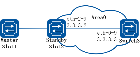
图5-17ospf gr
步骤 2进入配置模式
Switch# configure terminal
步骤 3Stacking设备和Switch3建立OSPF邻居
在Stacking slot1配置:
Switch1(config)#router ospf 1
Switch1(config-router)#router-id 1.1.1.1
Switch1(config-router)#network 3.3.3.0/24 area 0
Switch1(config-router)#exit
Switch1(config)#interface eth-2-9
Switch1(config-if)#no shutdown
Switch1(config-if)#no switchport
Switch1(config-if)#ip address 3.3.3.2/24
Switch1(config-if)# exit
在Switch3配置:
Switch3(config)#router ospf 1
Switch3(config-router)#router-id 3.3.3.3
Switch3(config-router)#network 3.3.3.0/24 area 0
Switch3(config-router)#exit
Switch3(config)#interface eth-0-9
Switch3(config-if)#no shutdown
Switch3(config-if)#no switchport
Switch3(config-if)#ip address 3.3.3.3/24
Switch3(config-if)# exit
使用下列命令查看ospf邻居:
Stacking slot1:
Switch1(config)# end
Switch1# show ip ospf neighbor
OSPF process 1:
Neighbor ID Pri State Dead Time Address Interface
3.3.3.3 1 Full/Backup 00:00:38 3.3.3.3 eth-2-9
Switch3:
Switch3(config)# end
Switch3# show ip ospf neighbor
OSPF process 0:
Neighbor ID Pri State Dead Time Address Interface
1.1.1.1 1 Full/DR 00:00:38 3.3.3.2 eth-0-9
步骤 4配置OSPF GR
在Stacking slot1配置GR Restarter:
Switch1# configure terminal
Switch1(config)# ospf restart ietf
Switch1(config)# ospf restart grace-period 300
在Switch3配置GR Helper:
Switch3# configure terminal
Switch3(config)# ospf restart helper enable
步骤 5退出配置模式
Switch(config)# end
步骤 6检查配置
使用下列命令查看ospf邻居,即使主板宕机,备板升主之后依然持续维持full邻居状态:
Stacking:
Switch1# show ip ospf neighbor
OSPF process 1:
Neighbor ID Pri State Dead Time Address Interface
3.3.3.3 1 Full/Backup 00:00:33 3.3.3.3 eth-2-9
Switch3:
Switch3# show ip ospf neighbor
OSPF process 0:
Neighbor ID Pri State Dead Time Address Interface
1.1.1.1 1 Full/DR 00:00:33 3.3.3.2 eth-0-9
5.4.1概述
简介
路由策略(Routing Policy)是为了改变网络流量所经过的途径而修改路由信息的技术,主要通过改变路由属性(包括可达性)来实现。地址前缀列表是路由策略的一种,作用比较灵活。一个地址前缀列表由前缀列表名标识。每个前缀列表可以包含多个表项,每个表项可以独立指定一个网络前缀形式的匹配范围,并用一个索引号来标识,索引号指明了进行匹配检查的顺序。在匹配的过程中,交换机按升序依次检查由索引号标识的各个表项。只要有某一表项满足条件,就意味着本次匹配过程结束,而不再进行下一个表项的匹配。
5.4.2配置举例
基础配置
步骤 1进入配置模式
Switch# configure terminal
步骤 2创建地址前缀列表
说明:创建一个地址前缀列表,如不指定sequence,则自动分配。支持不同的行为,如permit和deny。支持为列表创建说明字符串。
Switch(config)# ip prefix-list test seq 1 deny 35.0.0.0/8 le 16
Switch(config)# ip prefix-list test permit any
Switch(config)# ip prefix-list test description this prefix list is fot test
Switch(config)# ip prefix-list test permit 36.0.0.0/24
步骤 3退出配置模式
Switch(config)# end
步骤 4检查配置
使用下列命令,查看已经配置的地址前缀列表:
Switch# show ip prefix-list detail
Prefix-list list number: 1
Prefix-list entry number: 3
Prefix-list with the last deletion/insertion: test
ip prefix-list test:
Description: this prefix list is fot test
count: 3, range entries: 0, sequences: 1 - 10
seq 1 deny 35.0.0.0/8 le 16 (hit count: 0, refcount: 0)
seq 5 permit any (hit count: 0, refcount: 0)
seq 10 permit 36.0.0.0/24 (hit count: 0, refcount: 0)
配置Rip简单应用
步骤 1进入配置模式
Switch# configure terminal
步骤 2创建地址前缀列表
Switch(config)# ip prefix-list aa seq 11 deny 35.0.0.0/8 le 16
Switch(config)# ip prefix-list aa permit any
步骤 3在rip路由模式中应用前缀列表
Switch(config)# router rip
Switch(config-router)# distribute-list prefix aa out
Switch(config-router)# exit
步骤 4退出配置模式
Switch(config)# end
步骤 5检查配置
使用下列命令,查看已经配置的地址前缀列表:
Switch# show ip prefix-list
ip prefix-list aa: 2 entries
seq 11 deny 35.0.0.0/8 le 16
seq 15 permit any
使用下列命令,查看当前设备配置:
Switch# show running-config
Building configuration...
…
ip prefix-list aa seq 11 deny 35.0.0.0/8 le 16
ip prefix-list aa seq 15 permit any
…
router rip
distribute-list prefix aa out
配置Route-map简单应用
步骤 1进入配置模式
Switch# configure terminal
步骤 2创建地址前缀列表
Switch(config)# ip prefix-list aa seq 11 deny 3.3.3.0/8 le 24
Switch(config)# ip prefix-list aa permit any
步骤 3创建route map,匹配地址前缀列表
Switch(config)# route-map abc permit
Switch(config-route-map)# match ip address prefix-list aa
Switch(config-route-map)# set local-preference 200
Switch(config-route-map)# exit
Switch(config)# route-map abc permit 20
Switch(config-route-map)# exit
步骤 4进入bgp路由模式,并应用route map
Switch(config)# router bgp 1
Switch(config-router)# neighbor 1.1.1.2 remote-as 1
Switch(config-router)# neighbor 1.1.1.2 route-map abc out
Switch(config-router)# network 2.2.2.2/32
Switch(config-router)# network 3.3.3.3/32
步骤 5退出配置模式
Switch(config-router)# end
步骤 6检查配置
使用下列命令,查看已经配置的route map:
Switch # show route-map
route-map abc, permit, sequence 10
Match clauses:
ip address prefix-list aa
Set clauses:
local-preference 200
route-map abc, permit, sequence 20
Match clauses:
Set clauses:
使用下列命令,查看当前设备配置:
Switch # show running-config
Building configuration...
…
ip prefix-list aa seq 11 deny 3.3.3.0/8 le 24
ip prefix-list aa seq 15 permit any
!
!
route-map abc permit 10
match ip address prefix-list aa
set local-preference 200
!
route-map abc permit 20
…
router bgp 1
neighbor 1.1.1.2 remote-as 1
!
address-family ipv4
no synchronization
network 2.2.2.2 mask 255.255.255.255
network 3.3.3.3 mask 255.255.255.255
neighbor 1.1.1.2 activate
neighbor 1.1.1.2 route-map abc out
exit-address-family
!
address-family vpnv4 unicast
no synchronization
exit-address-family
5.5.1概述
简介
路由策略(Routing Policy)是为了改变网络流量所经过的途径而修改路由信息的技术,主要通过改变路由属性(包括可达性)来实现。
路由器在发布与接收路由信息时,可能需要实施一些策略,以便对路由信息进行过滤,例如只接收或发布满足一定条件的路由信息。一种路由协议可能需要引入其它的路由协议发现的路由信息,路由器在引入其它路由协议的路由信息时,可能只需要引入一部分满足条件的路由信息,并控制所引入的路由信息的某些属性,以使其满足本协议的要求。为实现路由策略,首先要定义将要实施路由策略的路由信息的特征,即定义一组匹配规则。可以以路由信息中的不同属性作为匹配依据进行设置,如目的地址、发布路由信息的路由器地址等。匹配规则可以预先设置好,然后再将它们应用于路由的发布、接收和引入等过程的路由策略中。
5.5.2配置举例
配置route-map应用到OSPF
步骤 1进入配置模式
Switch# configure terminal
步骤 2创建路由策略,设置规则和行为
![]()
route-map的名字最长20个字符,支持大小写和数字,在这个例子中为“abc”。支持permit和deny两种行为,如果不选则默认为permit。sequence number的范围是1-65535,在创建第一条规则时如未指定,则默认分配10。
Switch(config)# route-map abc permit
Switch(config-route-map)# match metric 20
Switch(config-route-map)# set tag 2
Switch(config-route-map)# exit
Switch(config)# route-map abc permit 20
Switch(config-route-map)# exit
步骤 3进入ospf路由模式,把RIP协议重分布到OSPF中,并且使用策略
Switch(config)# router ospf 100
Switch(config-router)# redistribute rip route-map abc
Switch(config-router)# exit
步骤 4退出配置模式
Switch(config)# end
步骤 5检查配置
Switch# show route-map
route-map abc, permit, sequence 10
Match clauses:
metric 20
Set clauses:
tag 2
route-map abc, permit, sequence 20
Match clauses:
Set clauses:
配置route-map应用到BGP
步骤 1进入配置模式
Switch# configure terminal
步骤 2创建ip访问控制列表
Switch(config)# ip access-list acl1
Switch(config-ip-acl)# permit any 3.3.3.0 0.0.0.255 any
Switch(config-ip-acl)# exit
步骤 3创建路由策略,匹配访问控制列表规则,并设置行为
Switch(config)# route-map abc permit
Switch(config-route-map)# match ip address acl1
Switch(config-route-map)# set local-preference 200
Switch(config-route-map)# exit
Switch(config)# route-map abc permit 20
Switch(config-route-map)# exit
步骤 4进入bgp路由模式,并且使用策略
Switch(config)# router bgp 1
Switch(config-router)# neighbor 1.1.1.2 remote-as 1
Switch(config-router)# neighbor 1.1.1.2 route-map abc out
Switch(config-router)# network 2.2.2.2/32
Switch(config-router)# network 3.3.3.3/32
Switch(config-router)# exit
步骤 5退出配置模式
Switch(config)# end
步骤 6检查配置
DUT1# show route-map
route-map abc, permit, sequence 10
Match clauses:
ip address acl1
Set clauses:
local-preference 200
route-map abc, permit, sequence 20
Match clauses:
Set clauses:
DUT2# show ip bgp
BGP table version is 6, local router ID is 1.1.1.2
Status codes: s suppressed, d damped, h history, * valid, > best, i - internal,
S Stale
Origin codes: i - IGP, e - EGP, ? - incomplete
Network Next Hop Metric LocPrf Weight Path
*>i2.2.2.2/32 1.1.1.1 0 100 0 i
*>i3.3.3.3/32 1.1.1.1 0 200 0 i
5.6.1概述
简介
与单纯根据IP报文的目的地址进行转发不同,策略路由是一种根据用户制定的策略进行路由转发的机制。
5.6.2配置举例
PBR配置
1.组网拓扑
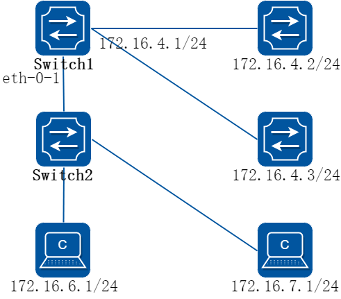
图5-18pbr
上图是策略路由的一个典型配置:可以在Switch1的eth-0-1端口上应用一个策略路由,源地址是172.16.6.1的报文将会被转发给172.16.4.2, 其余报文进行普通的路由转发,到172.16.4.3。
以下配置在Switch1上进行:
2.配置步骤
步骤 1进入配置模式
Switch# configure terminal
步骤 2创建ip访问控制列表,规则匹配源地址
Switch(config)# ip access-list acl1
Switch(config-ip-acl)# 10 permit any 172.16.6.0 0.0.0.255 any
Switch(config-ip-acl)# exit
步骤 3创建一个route map,匹配ip访问控制列表,并设置下一跳地址
Switch(config)# route-map rmap permit 10
Switch(config-route-map)# match ip address acl1
Switch(config-route-map)# set ip next-hop 172.16.4.2
Switch(config-route-map)# exit
步骤 4进入接口配置模式,配置接口属性,应用策略路由
Switch(config)# interface eth-0-1
Switch(config-if)# no switchport
Switch(config-if)# ip address 172.16.5.2/24
Switch(config-if)# no shutdown
Switch(config-if)# ip policy route-map rmap
Switch(config-if)# exit
步骤 5创建下一跳为172.16.4.3的静态路由(可选)
为实现“其余报文进行普通的路由转发”,可以使用静态路由来实现。也可以使用动态路由协议,视实际网络运行情况而定。
Switch(config)# ip route 0.0.0.0/0 172.16.4.3
步骤 6退出配置模式
Switch(config)# end
步骤 7检查配置
Switch# show ip policy route-map
Route-map interface
rmap eth-0-1
配置PBR与BFD联动
1.组网拓扑

图5-19pbr
上图是PBR与BFD联动的一个配置示例:根据PBR路由,switch2向端口eth-0-13转发报文,当switch4的eth-0-13口down时,bfd会话状态会切换到down状态,与之绑定的track 1也会转为down,PBR下一跳4.1.1.2会变为无效的,然后报文从switch2的eth-0-14口转发。
2.配置步骤
步骤 1在Switch1上配置
Switch1# configure terminal
Switch1(config)# interface eth-0-1
Switch1(config-if)# no shutdown
Switch1(config-if)# no switchport
Switch1(config-if)# ip address 1.1.1.1/24
Switch1(config-if)# exit
Switch1(config)# interface eth-0-9
Switch1(config-if)# no shutdown
Switch1(config-if)# no switchport
Switch1(config-if)# ip address 2.1.1.1/24
Switch1(config-if)# exit
Switch1(config)# ip route 5.1.1.0/24 2.1.1.2
Switch1(config)# ip route 6.1.1.0/24 2.1.1.2
Switch1(config)# end
步骤 2在Switch2上配置
Switch2# configure terminal
Switch2(config)# ip access-list acl1
Switch2(config-ip-acl)# 10 permit any host 2.1.1.1 any
Switch2(config-ip-acl)# quit
Switch2(config)# route-map rmap permit 10
Switch2(config-route-map)# match ip address acl1
Switch2(config-route-map)# set ip next-hop 4.1.1.2 track 1
Switch2(config-route-map)# quit
Switch2(config)# interface eth-0-9
Switch2(config-if)# no shutdown
Switch2(config-if)# no switchport
Switch2(config-if)# ip address 2.1.1.2/24
Switch2(config-if)# ip policy route-map rmap
Switch2(config-if)# exit
Switch2(config)# interface eth-0-13
Switch2(config-if)# no shutdown
Switch2(config-if)# no switchport
Switch2(config-if)# ip address 4.1.1.1/24
Switch2(config-if)# exit
Switch2(config)# interface eth-0-14
Switch2(config-if)# no shutdown
Switch2(config-if)# no switchport
Switch2(config-if)# ip address 5.1.1.1/24
Switch2(config-if)# exit
Switch2(config)# track 1 bfd source interface eth-0-13 destination 4.1.1.2
Switch2(config-track)# quit
Switch2(config)# ip route 1.1.1.0/24 2.1.1.1
Switch2(config)# ip route 6.1.1.0/24 5.1.1.2
Switch2(config)# end
步骤 3在Switch4上配置
Switch4# configure terminal
Switch4(config)# interface eth-0-1
Switch4(config-if)# no shutdown
Switch4(config-if)# no switchport
Switch4(config-if)# ip address 6.1.1.1/24
Switch4(config-if)# exit
Switch4(config)# interface eth-0-13
Switch4(config-if)# no shutdown
Switch4(config-if)# no switchport
Switch4(config-if)# ip address 4.1.1.2/24
Switch4(config-if)# exit
Switch4(config)# interface eth-0-14
Switch4(config-if)# no shutdown
Switch4(config-if)# no switchport
Switch4(config-if)# ip address 5.1.1.2/24
Switch4(config-if)# quit
Switch4(config)# track 1 bfd source interface eth-0-13 destination 4.1.1.1
Switch4(config-track)# quit
Switch4(config)# ip route 1.1.1.0/24 5.1.1.1
Switch4(config)# ip route 2.1.1.0/24 5.1.1.1
Switch4(config)# end
步骤 4ping 6.1.1.1 Switch2会向eth-0-13口转发报文
Switch1# ping 6.1.1.1
PING 6.1.1.1 (6.1.1.1) 56(84) bytes of data.
64 bytes from 6.1.1.1: icmp_seq=1 ttl=63 time=417 ms
64 bytes from 6.1.1.1: icmp_seq=2 ttl=63 time=428 ms
64 bytes from 6.1.1.1: icmp_seq=3 ttl=63 time=441 ms
64 bytes from 6.1.1.1: icmp_seq=4 ttl=63 time=469 ms
64 bytes from 6.1.1.1: icmp_seq=5 ttl=63 time=461 ms
--- 6.1.1.1 ping statistics ---
5 packets transmitted, 5 received, 0% packet loss, time 6810ms
rtt min/avg/max/mdev = 417.834/443.810/469.720/19.470 ms
步骤 5关闭Switch4的eth-0-13口
Switch4# configure terminal
Switch4(config)# interface eth-0-13
Switch4(config-if)# shutdown
Switch4(config-if)# end
步骤 6检查配置
Switch2# show track
Track 1
Type : BFD state
Source interface : eth-0-13
Destination IP : 4.1.1.2
BFD Local discr : 8192
rmap : pref 10 track 1
State : down
Switch2# show bfd session
Abbreviation:
LD: Local Discriminator. RD: Remote Discriminator
S: Single hop session. M: Multi hop session.
SD: Static Discriminator. DD: Dynamic Discriminator
SBFD: Seamless BFD
A: Admin down. D:Down. I:Init. U:Up.
============================================================================
LD RD TYPE ST UP-Time Remote-Addr Sbfd-Type VRF
8192 0 S-DD D 00:00:00 4.1.1.2 None default
Number of Sessions: 1
报文从Switch2的eth-0-14口转发
Switch1# ping 6.1.1.1
PING 6.1.1.1 (6.1.1.1) 56(84) bytes of data.
64 bytes from 6.1.1.1: icmp_seq=1 ttl=63 time=414 ms
64 bytes from 6.1.1.1: icmp_seq=2 ttl=63 time=432 ms
64 bytes from 6.1.1.1: icmp_seq=3 ttl=63 time=424 ms
64 bytes from 6.1.1.1: icmp_seq=4 ttl=63 time=525 ms
64 bytes from 6.1.1.1: icmp_seq=5 ttl=63 time=437 ms
--- 6.1.1.1 ping statistics ---
5 packets transmitted, 5 received, 0% packet loss, time 6563ms
rtt min/avg/max/mdev = 414.720/446.816/525.276/39.949 ms
5.7.1概述
简介
边界网关协议(BGP)是一个内部自治系统路由协议。
BGP通告系统的主要功能,是用其他的BGP系统来交换网络上的可达信息。这个网络可达信息包括自治系统(AS)中的可达性信息。这个信息,对构建一个可联通的AS(如果出现路由环路的话会被切断,以及在这个AS级别中,有些策略会被强制执行)来说,是足够的。
BGP-4 提供了一组机制,来支持无类域内路由(CIDR)[RFC1518, RFC1519]. 这些机制包括发布一组IP前缀的目的地址,已经消除BGP中“类”的概念。BGP-4 也引入了一些允许路由集合(包括AS路径的集合)这样的概念。
被BGP交换的路由信息只支持基于目的的范例,假定路由器只通过在IP报文头中的目的地址来转发报文。这样,反过来说,反而导致了这些策略决策是否可以被强制的使用BGP。BGP可以支持那些基于目的地址转发的策略。
原理描述
参考 1771, RFC 4271。
5.7.2配置举例
配置EBGP
1.组网拓扑
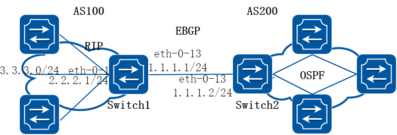
图5-20EBGP
2.配置步骤
步骤 1进入配置模式
Switch# configure terminal
步骤 2进入接口配置模式,配置接口属性
Switch1:
Switch1(config)# interface eth-0-13
Switch1(config-if)# no shutdown
Switch1(config-if)# no switchport
Switch1(config-if)# ip address 1.1.1.1/24
Switch1(config-if)# exit
Switch1(config)# interface eth-0-1
Switch1(config-if)# no shutdown
Switch1(config-if)# no switchport
Switch1(config-if)# ip address 2.2.2.1/24
Switch1(config-if)# exit
Switch2:
Switch2(config)# interface eth-0-13
Switch2(config-if)# no shutdown
Switch2(config-if)# no switchport
Switch2(config-if)# ip address 1.1.1.2/24
Switch2(config-if)# exit
步骤 3配置静态路由
Switch1:
Switch1(config)# ip route 3.3.3.0/24 2.2.2.2
步骤 4创建BGP路由实例,配置router id、邻居、宣告网络和配置重发布等属性
Switch1:
Switch1(config)# router bgp 100
Switch1(config-router)# bgp router-id 10.10.10.10
Switch1(config-router)# neighbor 1.1.1.2 remote-as 200
Switch1(config-router)# neighbor 1.1.1.2 ebgp-multihop
Switch1(config-router)# network 4.0.0.0/8
Switch1(config-router)# redistribute static
Switch1(config-router)# redistribute connected
Switch1(config-router)# exit
Switch2:
Switch2(config)# router bgp 200
Switch2(config-router)# bgp router-id 11.11.11.11
Switch2(config-router)# neighbor 1.1.1.1 remote-as 100
Switch2(config-router)# neighbor 1.1.1.1 ebgp-multihop
Switch2(config-router)# redistribute connected
Switch2(config-router)# exit
步骤 5退出配置模式
Switch(config)# end
步骤 6检查配置
Switch1:
Switch1# show ip bgp neighbors
BGP neighbor is 1.1.1.2, remote AS 200, local AS 100, external link
BGP version 4, remote router ID 11.11.11.11
BGP state = Established, up for 00:00:10
Last read 00:00:08, hold time is 180, keepalive interval is 60 seconds
Neighbor capabilities:
Route refresh: advertised and received (old and new)
4-Octet ASN Capability: advertised and received
Address family IPv4 Unicast: advertised and received
Received 5 messages, 1 notifications, 0 in queue
Sent 8 messages, 0 notifications, 0 in queue
Route refresh request: received 0, sent 0
Minimum time between advertisement runs is 30 seconds
For address family: IPv4 Unicast
BGP table version 1, neighbor version 1
Index 0, Offset 0, Mask 0x1
1 accepted prefixes
1 announced prefixes
Connections established 2; dropped 1
External BGP neighbor may be up to 255 hops away.
Local host: 1.1.1.1, Local port: 48036
Foreign host: 1.1.1.2, Foreign port: 179
Nexthop: 1.1.1.1
Nexthop global: ::
Nexthop local: ::
BGP connection: non shared network
Last Reset: 00:00:18, due to BGP Notification received
Notification Error Message: (Cease/Other Configuration Change.)
Switch2:
Switch2# show ip bgp neighbors
BGP neighbor is 1.1.1.1, remote AS 100, local AS 200, external link
BGP version 4, remote router ID 10.10.10.10
BGP state = Established, up for 00:00:16
Last read 00:00:15, hold time is 180, keepalive interval is 60 seconds
Neighbor capabilities:
Route refresh: advertised and received (old and new)
4-Octet ASN Capability: advertised and received
Address family IPv4 Unicast: advertised and received
Received 4 messages, 0 notifications, 0 in queue
Sent 6 messages, 1 notifications, 0 in queue
Route refresh request: received 0, sent 0
Minimum time between advertisement runs is 30 seconds
For address family: IPv4 Unicast
BGP table version 1, neighbor version 1
Index 1, Offset 0, Mask 0x2
1 accepted prefixes
1 announced prefixes
Connections established 1; dropped 1
External BGP neighbor may be up to 255 hops away.
Local host: 1.1.1.2, Local port: 179
Foreign host: 1.1.1.1, Foreign port: 48036
Nexthop: 1.1.1.2
Nexthop global: ::
Nexthop local: ::
BGP connection: non shared network
Last Reset: 00:00:19, due to BGP Notification sent
Notification Error Message: (Cease/Other Configuration Change.)
配置IBGP
1.组网拓扑
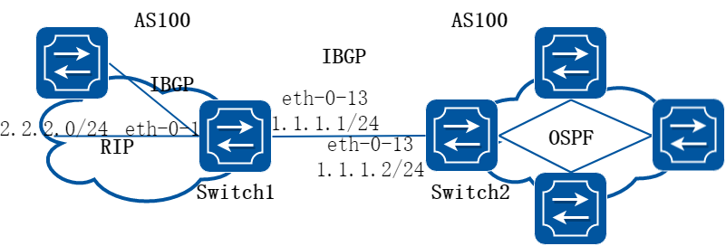
图5-21IBGP
2.配置步骤
步骤 1进入配置模式
Switch# configure terminal
步骤 2进入接口配置模式,配置接口属性
Switch1:
Switch1(config)# interface eth-0-1
Switch1(config-if)# no shutdown
Switch1(config-if)# no switchport
Switch1(config-if)# ip address 2.2.2.1/24
Switch1(config-if)# exit
Switch1(config)# interface eth-0-13
Switch1(config-if)# no shutdown
Switch1(config-if)# no switchport
Switch1(config-if)# ip address 1.1.1.1/24
Switch1(config-if)# exit
Switch1(config)#interface loopback 0
Switch1(config-if)# ip address 10.10.10.10/32
Switch1(config-if)# exit
Switch2:
Switch2(config)# interface eth-0-13
Switch2(config-if)# no shutdown
Switch2(config-if)# no switchport
Switch2(config-if)# ip address 1.1.1.2/24
Switch2(config-if)# exit
Switch2(config)# interface loopback 0
Switch2(config-if)# ip address 11.11.11.11/32
Switch2(config-if)# exit
步骤 3配置静态路由
Switch1:
Switch1(config)# ip route 11.11.11.11/32 1.1.1.2
Switch2:
Switch2(config)# ip route 10.10.10.10/32 1.1.1.1
步骤 4创建BGP路由实例,配置router id、邻居、宣告网络和配置重发布等属性
Switch1:
Switch1(config)# router bgp 100
Switch1(config-router)# bgp router-id 10.10.10.10
Switch1(config-router)# neighbor 11.11.11.11 remote-as 100
Switch1(config-router)# neighbor 11.11.11.11 update-source loopback 0
Switch1(config-router)# network 4.0.0.0/8
Switch1(config-router)# redistribute static
Switch1(config-router)# redistribute connected
Switch1(config-router)# exit
Switch2:
Switch2(config)# router bgp 100
Switch2(config-router)# bgp router-id 11.11.11.11
Switch2(config-router)# neighbor 10.10.10.10 remote-as 100
Switch2(config-router)# neighbor 10.10.10.10 update-source loopback 0
Switch2(config-router)# redistribute connected
Switch2(config-router)# exit
步骤 5退出配置模式
Switch(config)# end
步骤 6检查配置
Switch1:
Switch1# show ip bgp neighbors
BGP neighbor is 11.11.11.11, remote AS 100, local AS 100, internal link
BGP version 4, remote router ID 11.11.11.11
BGP state = Established, up for 00:00:06
Last read 00:00:06, hold time is 180, keepalive interval is 60 seconds
Neighbor capabilities:
Route refresh: advertised and received (old and new)
4-Octet ASN Capability: advertised and received
Address family IPv4 Unicast: advertised and received
Received 4 messages, 1 notifications, 0 in queue
Sent 4 messages, 0 notifications, 0 in queue
Route refresh request: received 0, sent 0
Minimum time between advertisement runs is 5 seconds
Update source is loopback0
For address family: IPv4 Unicast
BGP table version 1, neighbor version 1
Index 0, Offset 0, Mask 0x1
0 accepted prefixes
0 announced prefixes
Connections established 2; dropped 1
Local host: 10.10.10.10, Local port: 179
Foreign host: 11.11.11.11, Foreign port: 38689
Nexthop: 10.10.10.10
Nexthop global: ::
Nexthop local: ::
BGP connection: non shared network
Last Reset: 00:00:15, due to BGP Notification received
Notification Error Message: (Cease/Other Configuration Change.)
Switch2:
Switch2# show ip bgp neighbors
BGP neighbor is 10.10.10.10, remote AS 100, local AS 100, internal link
BGP version 4, remote router ID 10.10.10.10
BGP state = Established, up for 00:00:00
Last read 00:00:00, hold time is 180, keepalive interval is 60 seconds
Neighbor capabilities:
Route refresh: advertised and received (old and new)
4-Octet ASN Capability: advertised and received
Address family IPv4 Unicast: advertised and received
Received 4 messages, 0 notifications, 0 in queue
Sent 4 messages, 1 notifications, 0 in queue
Route refresh request: received 0, sent 0
Minimum time between advertisement runs is 5 seconds
Update source is loopback0
For address family: IPv4 Unicast
BGP table version 1, neighbor version 0
Index 0, Offset 0, Mask 0x1
0 accepted prefixes
0 announced prefixes
Connections established 2; dropped 1
Local host: 11.11.11.11, Local port: 38689
Foreign host: 10.10.10.10, Foreign port: 179
Nexthop: 11.11.11.11
Nexthop global: ::
Nexthop local: ::
BGP connection: non shared network
Last Reset: 00:00:10, due to BGP Notification sent
Notification Error Message: (Cease/Other Configuration Change.)
配置BGP 网段侦听
1.组网拓扑
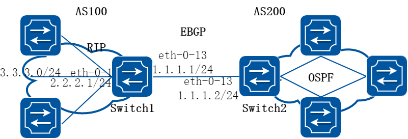
图5-22EBGP
2.配置步骤
步骤 1进入配置模式
Switch# configure terminal
步骤 2进入接口配置模式,配置接口属性
Switch1:
Switch1(config)# interface eth-0-13
Switch1(config-if)# no shutdown
Switch1(config-if)# no switchport
Switch1(config-if)# ip address 1.1.1.1/24
Switch1(config-if)# exit
Switch2:
Switch2(config)# interface eth-0-13
Switch2(config-if)# no shutdown
Switch2(config-if)# no switchport
Switch2(config-if)# ip address 1.1.1.2/24
Switch2(config-if)# exit
步骤 3创建BGP路由实例,配置router id、邻居、宣告网络和配置重发布等属性
Switch1:
Switch1(config)# router bgp 100
Switch1(config-router)# bgp router-id 10.10.10.10
Switch1(config-router)# neighbor group1 peer-group listen external
Switch1(config-router)# neighbor group1 listen-as 200
Switch1(config-router)# neighbor group1 listen-net 1.1.1.0/24
Switch1(config-router)# exit
Switch2:
Switch2(config)# router bgp 200
Switch2(config-router)# bgp router-id 11.11.11.11
Switch2(config-router)# neighbor 1.1.1.1 remote-as 100
Switch2(config-router)# exit
步骤 4退出配置模式
Switch(config)# end
步骤 5检查配置
Switch1:
Switch1# show ip bgp neighbors
BGP neighbor is 1.1.1.2, remote AS 200, local AS 100, external link
Member of peer-group group1 for session parameters, learned by bgp listen-net dynamically
BGP version 4, remote router ID 11.11.11.11
BGP state = Established, up for 00:00:01
Last read 00:00:02, hold time is 180, keepalive interval is 60 seconds
Neighbor capabilities:
Route refresh: advertised and received (old and new)
4-Octet ASN Capability: advertised and received
Address family IPv4 Unicast: advertised and received
Received 2 messages, 0 notifications, 0 in queue
Sent 2 messages, 0 notifications, 0 in queue
Route refresh request: received 0, sent 0
Minimum time between advertisement runs is 30 seconds
For address family: IPv4 Unicast
BGP table version 1, neighbor version 0
Index 1, Offset 0, Mask 0x2
group1 peer-group member
0 accepted prefixes
0 announced prefixes
Connections established 1; dropped 0
Local host: 1.1.1.1, Local port: 48022
Foreign host: 1.1.1.2, Foreign port: 179
Nexthop: 1.1.1.1
Nexthop global: ::
Nexthop local: ::
BGP connection: non shared network
Switch2:
Switch2# show ip bgp neighbors
BGP neighbor is 1.1.1.1, remote AS 100, local AS 200, external link
BGP version 4, remote router ID 10.10.10.10
BGP state = Established, up for 00:00:07
Last read 00:00:07, hold time is 180, keepalive interval is 60 seconds
Neighbor capabilities:
Route refresh: advertised and received (old and new)
4-Octet ASN Capability: advertised and received
Address family IPv4 Unicast: advertised and received
Received 2 messages, 0 notifications, 0 in queue
Sent 4 messages, 0 notifications, 0 in queue
Route refresh request: received 0, sent 0
Minimum time between advertisement runs is 30 seconds
For address family: IPv4 Unicast
BGP table version 1, neighbor version 1
Index 1, Offset 0, Mask 0x2
0 accepted prefixes
0 announced prefixes
Connections established 1; dropped 0
Local host: 1.1.1.2, Local port: 179
Foreign host: 1.1.1.1, Foreign port: 48022
Nexthop: 1.1.1.2
Nexthop global: ::
Nexthop local: ::
BGP connection: non shared network
5.8.1概述
简介
中间系统到中间系统ISIS是一种链路状态路由协议,使用最短路径优先SPF算法进行 路由算法,实际上与OSPF非常相似,它也使用Hello协议寻找毗邻节点,使用一个传播协议发送链接信息。ISIS可以在不同的子网上操作,包括广播型的LAN、WAN和点到点链路。
原理描述
1.NET
NET(Network Entity Title,网络实体名称)指示的是IS本身的网络层信息,不包括传输层信息(SEL=0),可以看作是一类特殊的NSAP,即SEL为0的NSAP地址。因此,NET的长度与NSAP的相同,最多为20个字节,最少为8个字节。
通常情况下,一台路由器配置一个NET即可,当区域需要重新划分时,例如将多个区域合并,或者将一个区域划分为多个区域,这种情况下配置多个NET可以在重新配置时仍然能够保证路由的正确性。由于一台路由器默认最多可配置3个区域地址,所以最多也只能配置3个NET。在配置多个NET时,必须保证它们的System ID都相同。
例如NET为:ab.cdef.1234.5678.9abc.00,则其中Area为ab.cdef,System ID为1234.5678.9abc,SEL为00。
2.ISIS区域
• Level-1路由器 Level-1路由器负责区域内的路由,它只与属于同一区域的Level-1和Level-1-2路由器形成邻居关系,维护一个Level-1的LSDB,该LSDB包含本区域的路由信息,到区域外的报文转发给最近的Level-1-2路由器。
• Level-2路由器 Level-2路由器负责区域间的路由,可以与同一区域或者其它区域的Level-2和Level-1-2路由器形成邻居关系,维护一个Level-2的LSDB,该LSDB包含区域间的路由信息。所有Level-2路由器和Level-1-2路由器组成路由域的骨干网,负责在不同区域间通信,路由域中的Level-2路由器必须是物理连续的,以保证骨干网的连续性。只有Level-2路由器才能直接与路由域外的路由器交换数据报文或路由信息。
• Level-1-2路由器 同时属于Level-1和Level-2的路由器称为Level-1-2路由器,可以与同一区域的Level-1和Level-1-2路由器形成Level-1邻居关系,也可以与同一区域或者其他区域的Level-2和Level-1-2路由器形成Level-2的邻居关系。Level-1路由器必须通过Level-1-2路由器才能连接至其他区域。Level-1-2路由器维护两个LSDB,Level-1的LSDB用于区域内路由,Level-2的LSDB用于区域间路由。
5.8.2配置举例
配置基本ISIS
1.组网拓扑

图5-23ISIS
2.配置步骤
步骤 1进入配置模式
Switch# configure terminal
步骤 2创建isis实例,配置net
Switch1的配置:
Switch1(config)# router isis
Switch1(config-router)# net 10.0000.0000.0001.00
Switch1(config-router)# exit
Switch2的配置:
Switch2(config)# router isis
Switch2(config-router)# net 10.0000.0000.0002.00
Switch2(config-router)# exit
步骤 3接口使能ipv4 isis
Switch1的配置:
Switch1(config)# interface eth-0-9
Switch1(config-if)# no switchport
Switch1(config-if)# ip address 10.10.10.10/24
Switch1(config-if)# ip router isis
Switch1(config)# interface loopback 0
Switch1(config-if)# ip address 1.1.1.1/32
Switch1(config-if)# ip router isis
Switch1(config-if)# exit
Switch2的配置:
Switch2(config)# interface eth-0-9
Switch2(config-if)# no switchport
Switch2(config-if)# ip address 10.10.10.11/24
Switch2(config-if)# ip router isis
Switch2(config)# interface loopback 0
Switch2(config-if)# ip address 2.2.2.2/32
Switch2(config-if)# ip router isis
Switch2(config-if)# exit
步骤 4退出配置模式
Switch(config)# end
步骤 5检查配置
Switch1 显示结果:
Switch1# show clns neighbors
Area (null):
System Id Interface SNPA State Holdtime Type Protocol
0000.0000.0002 eth-0-9 4a98.a825.3d00 Up 21 L1 IS-IS
Up 21 L2 IS-IS
Switch1# show isis database verbose
Area (null):
IS-IS Level-1 Link State Database:
LSPID LSP Seq Num LSP Checksum LSP Holdtime ATT/P/OL
0000.0000.0001.00-00* 0x00000004 0x3244 1082 0/0/0
Area Address: 10
NLPID: IPV4
IP Address: 10.10.10.10
Metric: 10 IS 0000.0000.0001.01
Metric: 10 IP 10.10.10.0 255.255.255.0
Metric: 10 IP 1.1.1.1 255.255.255.255
0000.0000.0001.01-00* 0x00000001 0x21B9 895 0/0/0
Metric: 0 IS 0000.0000.0001.00
Metric: 0 IS 0000.0000.0002.00
0000.0000.0002.00-00 0x00000004 0xFA75 1076 0/0/0
Area Address: 10
NLPID: IPV4
IP Address: 10.10.10.11
Metric: 10 IS 0000.0000.0001.01
Metric: 10 IP 10.10.10.0 255.255.255.0
Metric: 10 IP 2.2.2.2 255.255.255.255
IS-IS Level-2 Link State Database:
LSPID LSP Seq Num LSP Checksum LSP Holdtime ATT/P/OL
0000.0000.0001.00-00* 0x00000005 0xFCCE 1109 0/0/0
Area Address: 10
NLPID: IPV4
IP Address: 10.10.10.10
Metric: 10 IS 0000.0000.0001.01
Metric: 10 IP 10.10.10.0 255.255.255.0
Metric: 20 IP 2.2.2.2 255.255.255.255
Metric: 10 IP 1.1.1.1 255.255.255.255
0000.0000.0001.01-00* 0x00000001 0x21B9 895 0/0/0
Metric: 0 IS 0000.0000.0001.00
Metric: 0 IS 0000.0000.0002.00
0000.0000.0002.00-00 0x00000005 0x7B4E 1107 0/0/0
Area Address: 10
NLPID: IPV4
IP Address: 10.10.10.11
Metric: 10 IS 0000.0000.0001.01
Metric: 10 IP 10.10.10.0 255.255.255.0
Metric: 10 IP 2.2.2.2 255.255.255.255
Metric: 20 IP 1.1.1.1 255.255.255.255
Switch1# show ip isis route
Codes: C - connected, E - external, L1 - IS-IS level-1, L2 - IS-IS level-2
ia - IS-IS inter area, D - discard, e - external metric
Area (null):
Destination Metric Next-Hop Interface Tag
C 1.1.1.1/32 10 -- loopback0 0
L1 2.2.2.2/32 20 10.10.10.11 eth-0-9 0
C 10.10.10.0/24 10 -- eth-0-9 0
Switch2 显示结果:
Switch2# show clns neighbors
Area (null):
System Id Interface SNPA State Holdtime Type Protocol
0000.0000.0001 eth-0-9 a821.1873.ae00 Up 9 L1 IS-IS
Up 9 L2 IS-IS
Switch2# show isis database verbose
Area (null):
IS-IS Level-1 Link State Database:
LSPID LSP Seq Num LSP Checksum LSP Holdtime ATT/P/OL
0000.0000.0001.00-00 0x00000004 0x3244 934 0/0/0
Area Address: 10
NLPID: IPV4
IP Address: 10.10.10.10
Metric: 10 IS 0000.0000.0001.01
Metric: 10 IP 10.10.10.0 255.255.255.0
Metric: 10 IP 1.1.1.1 255.255.255.255
0000.0000.0001.01-00 0x00000001 0x21B9 745 0/0/0
Metric: 0 IS 0000.0000.0001.00
Metric: 0 IS 0000.0000.0002.00
0000.0000.0002.00-00* 0x00000004 0xFA75 930 0/0/0
Area Address: 10
NLPID: IPV4
IP Address: 10.10.10.11
Metric: 10 IS 0000.0000.0001.01
Metric: 10 IP 10.10.10.0 255.255.255.0
Metric: 10 IP 2.2.2.2 255.255.255.255
IS-IS Level-2 Link State Database:
LSPID LSP Seq Num LSP Checksum LSP Holdtime ATT/P/OL
0000.0000.0001.00-00 0x00000005 0xFCCE 961 0/0/0
Area Address: 10
NLPID: IPV4
IP Address: 10.10.10.10
Metric: 10 IS 0000.0000.0001.01
Metric: 10 IP 10.10.10.0 255.255.255.0
Metric: 20 IP 2.2.2.2 255.255.255.255
Metric: 10 IP 1.1.1.1 255.255.255.255
0000.0000.0001.01-00 0x00000001 0x21B9 747 0/0/0
Metric: 0 IS 0000.0000.0001.00
Metric: 0 IS 0000.0000.0002.00
0000.0000.0002.00-00* 0x00000005 0x7B4E 960 0/0/0
Area Address: 10
NLPID: IPV4
IP Address: 10.10.10.11
Metric: 10 IS 0000.0000.0001.01
Metric: 10 IP 10.10.10.0 255.255.255.0
Metric: 10 IP 2.2.2.2 255.255.255.255
Metric: 20 IP 1.1.1.1 255.255.255.255
Switch2# show ip isis route
Codes: C - connected, E - external, L1 - IS-IS level-1, L2 - IS-IS level-2
ia - IS-IS inter area, D - discard, e - external metric
Area (null):
Destination Metric Next-Hop Interface Tag
L1 1.1.1.1/32 20 10.10.10.10 eth-0-9 0
C 2.2.2.2/32 10 -- loopback0 0
C 10.10.10.0/24 10 -- eth-0-9 0